27
Marathon Electric (a division of RBC Manufacturing Corp.) reserves the right to change specications and this manual without notice.
Revised 06/2011
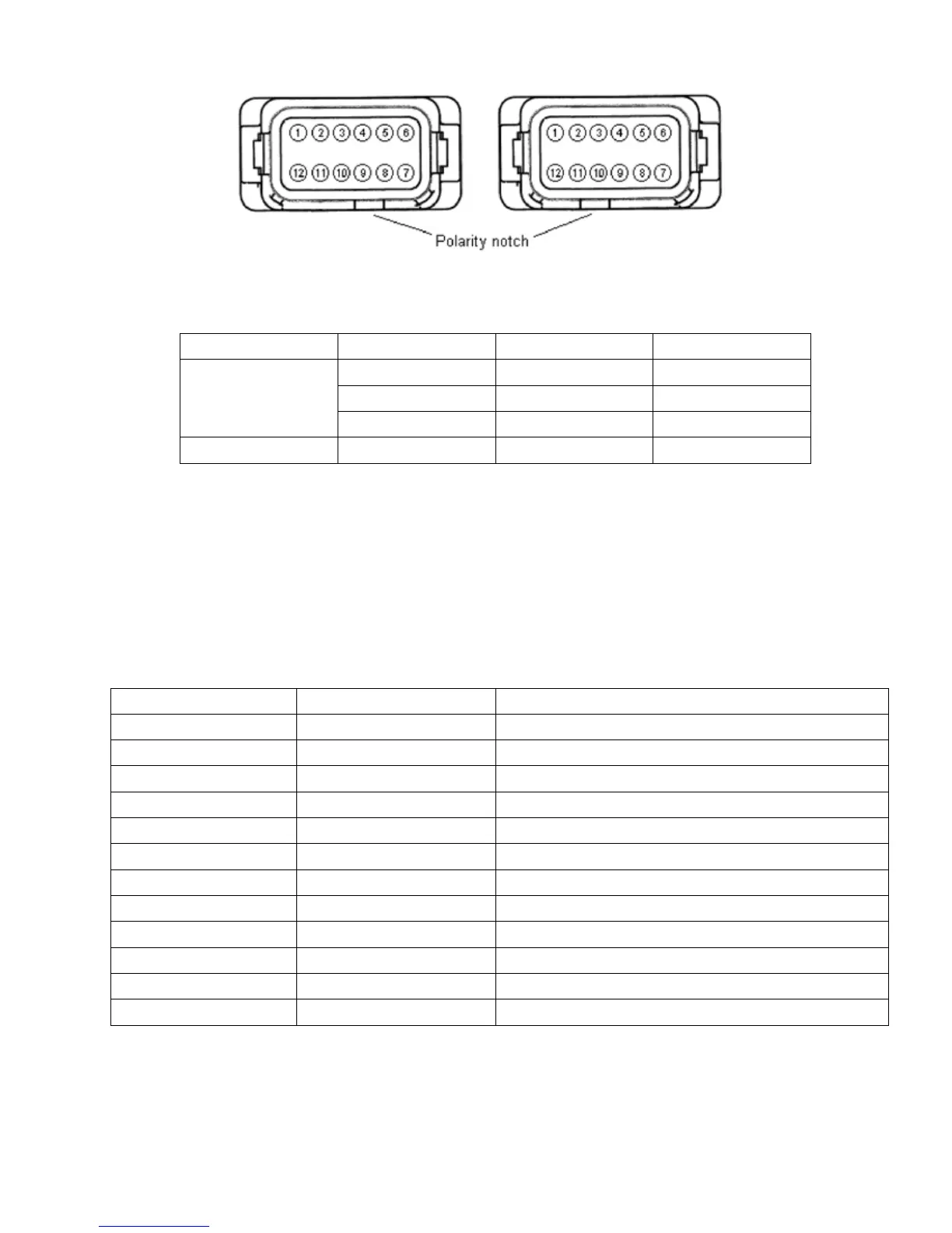
Figure4-4.SystemConnectorsJ1(left)andJ2(right)TerminalPosition
Sensing Phase X1 Terminal X2 Terminal
A J2-1 J2-12
3-Phase B J2-2 J2-11
C J2-3 J2-10
1-Phase B CT1 CT2
Table 4-2. Current Transformer Connection Terminals
Note: The current transformer primaries are aligned such that the H1 face is nearest to the generator for typical
donut-style current transformers.
Pin Number Name Description
1 AUX IN (+) Auxiliary input positive
2 UP UP contact input (active low)
3 DOWN DOWN contact input (active low)
4 CGND Input common
5 AUX_LOOP Auxiliarycurrentloopjumper
6 CONTACT1 Contact output
7 CONTACT2 Contact output
8 AUX_LOOP Auxiliarycurrentloopjumper
9 Reserved
10 DROOP_OFF Droop disable contact input (active low)
11 EXCITATION_OFF Excitation disable contact input (active low)
12 AUX IN (-) Auxiliary input negative
Table4-3.ConnectorJ1SystemConnections