28
Marathon Electric (a division of RBC Manufacturing Corp.) reserves the right to change specications and this manual without notice.
Revised 06/2011
UP and DOWN Contact Inputs
RemotesetpointadjustmentmaybeaccomplishedbyconnectingaSPDTmomentarycontactswitchtotheJ1
connectorUP andDOWNcontacts. To connectthis switch, thecommon terminalmustbe connected toJ1-4
(CGND).TheothertwoswitchterminalsareconnectedtoJ1-2(UP)andJ1-3(DOWN).RefertoSection3–Fea-
tures and Protection for a detailed description of the UP and DOWN contact function.
Parallel Generator Compensation Enable/Disable (DROOP OFF)
A user can enable or disable the integrated load sharing function of the regulator by opening or closing contact
betweenJ1-10(DROOPOFF)andJ1-4(CGND).Closingthecontactdisablesthedroopfunction.RefertoSection
3 – Features and Protection for a detailed description of the Load Sharing function.
Excitation Enable/Disable (EXCITATION OFF)
AusercanenableordisableexcitationbyopeningorclosingcontactbetweenJ1-11(EXCITATIONOFF)and
J1-4(CGND).Closingthecontactdisablesexcitation.RefertoSection3–FeaturesandProtectionforade-
tailed description of the Excitation Off function.
Auxiliary Input (AUX_IN (+), AUX_IN (-), and AUX_LOOP)
This input allows a user to control the regulator with an auxiliary piece of equipment by connecting a voltage
sourcetoJ1-1(AUXIN+)andJ1-12(AUXIN-).Theregulatorcanalsobeconguredtoacceptavoltageor
current to be metered on this input. Refer to Section 3 – Features and Protection for a detailed description of the
Auxiliary input function.
Contact Output (CONTACT1 and CONTACT2)
TheoutputcontactmaybeaccessedatconnectorJ1,viaterminalsJ1-6(CONTACT1)andJ1-7(CONTACT2).The
relay output is normally open and closes when the regulator goes into a fault condition.
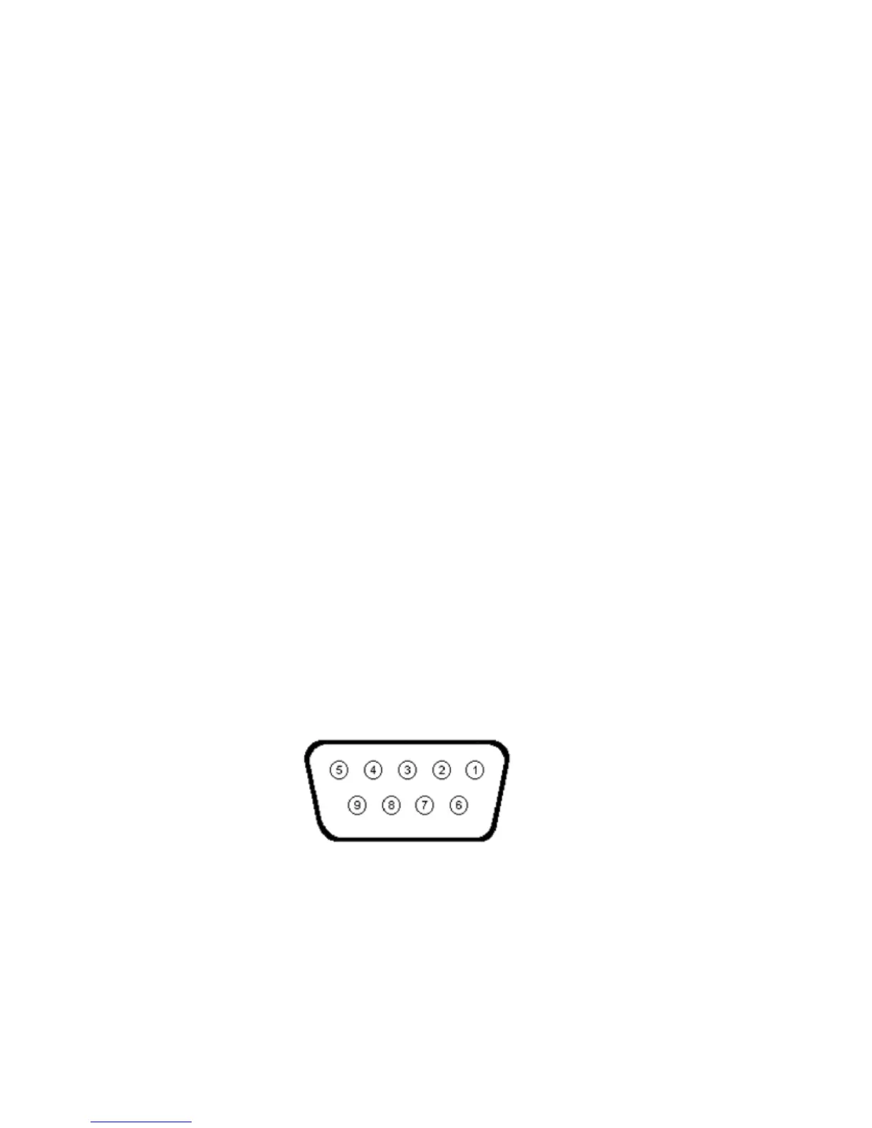
Figure 4-5. MODBUS Communication Port Terminal Positions