29
Marathon Electric (a division of RBC Manufacturing Corp.) reserves the right to change specications and this manual without notice.
Revised 06/2011
Table 4-4. MODBUS Communication Port Pin Functions
Pin Number Function Name
1 N/C
2 Receive Data RXD
3 Transmit Data TXD
4 Data Terminal Ready DTR
5 Signal Ground GND
6 Data Set Ready DSR
7 Ready To Send RTS
8 N/C
9 N/C
Note: If serial port does not support DTR and RTS functions, then these lines must be connected to serial port
positive supply voltage of Data Terminal Equipment.
Serial Communication Port
The RS-232 port on the rear panel uses a DB-9 female connector. Figure 4-5 and Table 4-4 illustrate the pin
assignments of the communication port from the perspective of the PC. A standard communication cable
terminated with a DB-9 male connector is used for PC interface with the DVR
®
2000E+.
Note: Do not use a “cross-over” or “null-modem” cable.
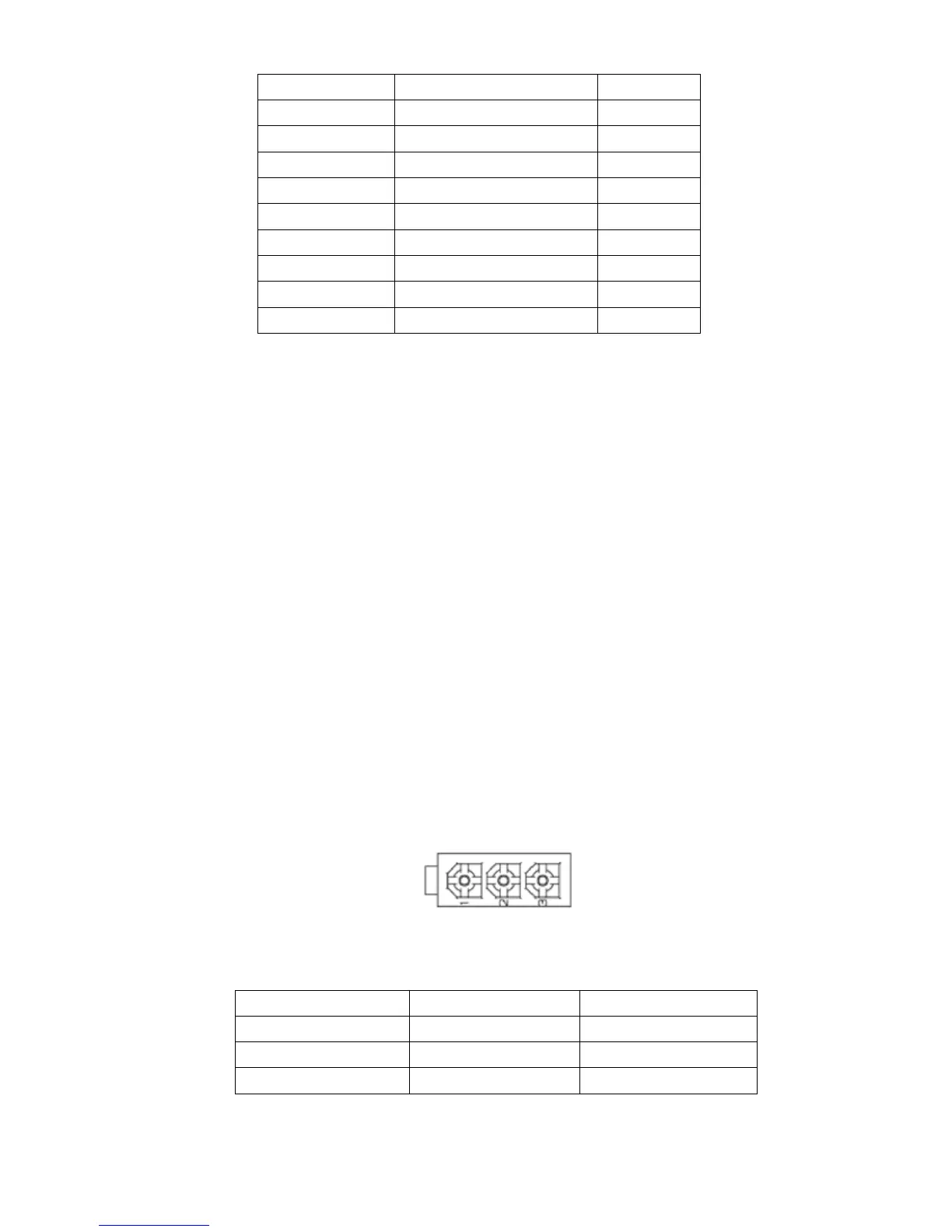
CAN J1939 Communication Port (J3)
TheCANportontherearpanelusesanAMP/TycoMiniMat-N-Lokconnector.Figure4-6illustratesthepinas-
signments of the CAN port and Table 4-5 identifies the pin functions of the CAN port.
Table 4-4. MODBUS Communication Port Pin Functions
Pin Number Function Name
1 CAN High CAN_H
2 CAN Low CAN_L
3 CAN Ground CAN_GND
Table4-5.ConnectorJ3CANPortPinFunctions