30
Marathon Electric (a division of RBC Manufacturing Corp.) reserves the right to change specications and this manual without notice.
Revised 06/2011
DVR
®
2000E+ Connections for Typical Applications
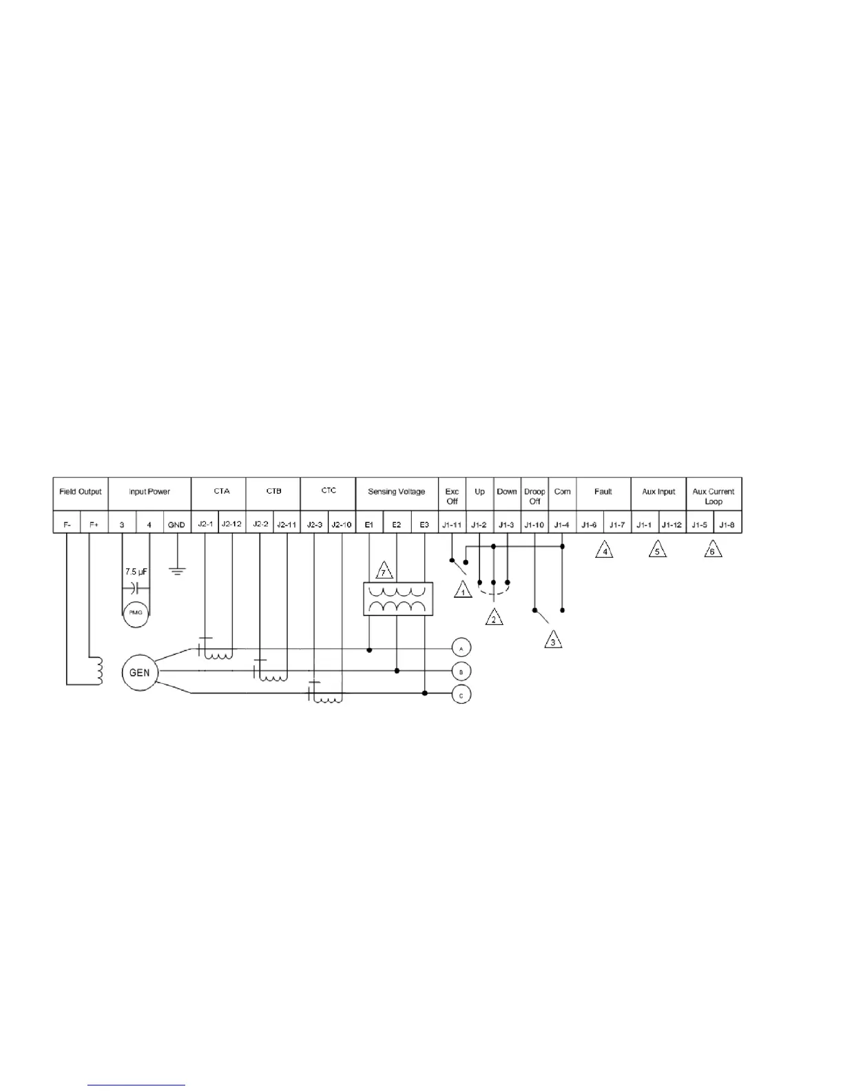
Figures 4-7 through 4-10 illustrate typical applications using the DVR
®
2000E+.
•Figure4-7showsanapplicationwheretheregulatorisconnectedforthree-phasevoltagesensingand
three-phase current sensing.
•Figure4-8showsanapplicationwheretheregulatorisconnectedforthree-phasevoltagesensingand
single-phase current sensing.
•Figure4-9showsanapplicationwheretheregulatorisconnectedforwithsingle-phasevoltagesensing
and single-phase current sensing.
•Figure4-10illustratesanapplicationwithasingle-phasegenerator.
Figure 4-11 and 4-12 illustrate how the regulators can be interconnected for use in Cross-Current (Reactive
Differential) applications. When operating in Cross-Current mode, attention must be paid to the use of the burden
resistor shown in Figure 4-11 and 4-12. The burden resistor should have a value of approximately 10 times the
cross current loop resistance for proper differential operation. The value of 0.1 ohm is a suggested value. The
volt-ampere (VA) capacity of the paralleling current transformers should be considered when sizing the burden
resistor.
NOTESk:
1. Excitation enabled when switch is open and disabled when switch is closed. Switch supplied by others.
2.SPDT,springreturntocenter-offpositiontypeswitchforremotesetpointadjust.Switchsuppliedbyothers.
3. Droop enabled when switch is open and disabled when switch is closed. Switch supplied by others.
4. Normally open contact closes in a fault condition.
5. Analog signal input when Auxiliary is configured for control or metering.
6. Should be shorted when Auxiliary is configured as 4-20 mA metering input.
7. Sensing potential transformer is required if generator output voltage exceeds 600 Volts.
Figure 4-7. Typical Connections with ABC Rotation, Three-Phase Voltage Sensing and
Three-Phase Current Sensing