Home
Mariner
Outboard Motor
150 OPTIMAX
Mariner 150 OPTIMAX User Manual
5
of 1
of 1 rating
490 pages
Give review
Manual
Specs
To Next Page
To Next Page
To Previous Page
To Previous Page
Loading...
POWERHEAD
Page 4A-8
90-855347R1 JANUARY
1999
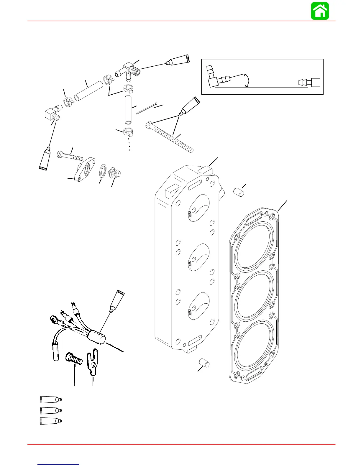
Cylinder Head
3
4
5
6
7
8
9
11
10
14
15
16
1
2
13
4
12
13
A
13
13
9
9
6
14
15
°
Back of Engine
W
ater Fitting Orientation
Looking Down at T
op of Block
Dielectric Grease (92-823506--1)
6
Loctite PST Pipe Sealant (92-809822)
9
14
2 Cycle Outboard Oil (92-13249A24)
A = TO STRAIGHT FITTING ON BACK OF EXHAUST PLA
TE
230
232
Table of Contents
Cleanliness and Care of Outboard Motor
3
Page Numbering
3
Service Manual Outline
4
Important Information
5
Specifications
5
Master Specifications
5
Table of Contents
8
Maintenance
8
Gear Case Lubricant Capacity
8
Special Tools
9
Quicksilver Lubricant/Sealant
9
Inspection and Maintenance Schedule
11
Before each Use
11
After each Use
11
Every 100 Hours of Use or Once Yearly, Whichever Occurs First
11
Flushing Engine
12
Flushing Cooling System - Using Cowl Flush Plug
12
Flushing Cooling System - Using Flushing Attachment 44357A2
12
Fuel System
13
Fuel Line Inspection
13
Water Separating Fuel Filter
13
Corrosion Control Anode
14
Spark Plug Inspection
14
Battery Inspection
15
Fuse Replacement
15
Compressor Air Intake Filter
16
Lubrication Points
16
Removal
16
Installation
16
Checking Power Trim Fluid
18
Gear Case Lubrication
19
Storage Preparation
20
General Information
22
Serial Number Location
22
Conditions Affecting Performance
23
Weather
23
Boat
24
Trim
25
Engine Compression
27
Following Complete Submersion
28
Salt Water Submersion
28
Submerged While Running
28
Model 135/150 DFI Powerhead Front View
30
Model 135/150 DFI Powerhead Starboard View 1C-10
31
Model 135/150 DFI Powerhead Port View
32
Model 135/150 DFI Powerhead Top View
33
Model 135/150 DFI Powerhead Aft View
34
Painting Procedures
35
Cleaning & Painting Aluminum Propellers & Gear Housings
35
Decal Application
36
Decal Removal
36
Instructions for "Wet" Application
36
Outboard Motor Installation
38
Installation Specifications
38
Lifting Outboard
38
Installing Outboard to Boat Transom
39
Determining Recommended Outboard Mounting Height
39
Installing Outboard
40
Drilling Outboard Mounting Holes
40
Steering Cable
41
Securing Outboard to Boat Transom
41
Steering Link Rod
42
Electrical, Hoses and Control Cables
43
Installation Note
43
Remote Wiring Harness
43
Warning Gauge Harness
44
Battery Cables
45
Single Outboard
45
Dual Outboard
45
Shift Cable
46
Counter Rotation Outboards
46
Installation
47
Throttle Cable
49
Installation
49
Front Clamp Reassembly
50
Filling Fuel System
51
Oil Injection Set-Up
51
Priming the Oil Injection Pump
52
Purging Air from the Engine Oil Tank
53
Trim "In" Angle Adjustment
53
Trim Tab Adjustment
54
Models Without Power Steering
54
Models with Power Steering
54
Electrical
55
Ignition
55
Special Tools
56
Electrical Components
58
Theory of Operation
60
Ignition Component Description
60
Electronic Control Module (ECM)
60
Flywheel
61
Ignition Coils
61
Throttle Position Sensor (TPS)
61
Charging System Alternator
61
Crank Position Sensor
61
Temperature Sensor
62
Manifold Absolute Pressure (MAP) Sensor
63
Air Temperature Sensor
63
Direct Injectors
63
Disconnecting Harness Connectors from Ignition Coils And/Or Injectors
63
Fuel Injectors
63
Troubleshooting
63
Troubleshooting Without Digital Diagnostic Terminal
64
Troubleshooting with the Digital Diagnostic Terminal
65
Notes
66
DDT Functions – Optimax Models Software Version 4.0 and 4.1
67
DFI Troubleshooting Guide
68
Ignition Components Removal and Installation
71
Flywheel Cover Removal and Installation
71
Electronic Control Module (ECM)
72
Ignition Module (Coil)
73
Crank Position Sensor
74
Throttle Position Sensors (TPS)
74
Charging & Starting System
75
Battery Cable Size
76
Replacement Parts
76
Recommended Battery
76
Battery
77
Precautions
77
Special Tools
77
Charging a Discharged Battery
78
Winter Storage of Batteries
78
Flywheel Removal and Installation
79
Installation
80
Flywheel/Alternator
82
System Components
84
Precautions
84
Alternator Description
85
Diagnosis of Alternator System on Engine
85
Alternator Assembly
86
Alternator System Circuitry Test
87
Output Circuit
87
Sensing Circuit
87
Voltage Output
88
Current Output
89
Repair
89
Removal
89
Disassembly and Test
90
Rotor Test
92
Stator Test
93
Reassembly
94
Pulley
95
Alternator Belt Tension Adjustment
96
Installation
96
Starter Motor Amperes Draw
97
Starter System Components
97
Description
97
Starter Motor
98
Troubleshooting the Starter Circuit
99
Starter Circuit Troubleshooting Flow Chart
100
Starter Removal and Installation
101
Installation
102
Disassembly
102
Starter Cleaning, Inspection and Testing
104
Cleaning and Inspection
104
Starter Reassembly
106
Starter Solenoid Test
108
Commander 2000 Key Switch Test
109
Timing, Synchronizing & Adjusting
110
Special Tools
111
Crank Position Sensor
113
Throttle Cam Adjustment
114
Maximum Throttle
114
Idle Speed
115
Throttle Position Sensor (TPS) Adjustment
115
Throttle Plate Screw
115
Wiring Diagrams
116
Power Trim Wiring Diagram
117
Instrument Wiring Connections
118
Commander 3000 Classic Panel Remote Control 2D-4
119
Commander 3000 Panel Remote Control
120
Instrument/Lanyard Stop Switch Wiring Diagram
121
Oil Level Gauge Wiring Diagram
122
Instrument/Lanyard Stop Switch Wiring Diagram (Dual Outboard)
123
QSI Gauge Wiring Diagrams
125
Tachometer Wiring Diagram
125
Water Temperature Gauge
126
Oil Level Gauge Wiring
127
Engine Synchronizer Wiring Diagram
129
Maintenance
130
Multi-Function Gauge
131
Dip Switch Setting/Testing
131
Outboard Multi-Function Gauge Setting
132
Warning System
132
Warning System Signals
133
Warning System Operation
134
Panel Mount Remote Control Wiring Installation 2D-22
137
1998 Model 135/150 DFI Wiring Diagram
138
1999 Model 135/150 DFI Wiring Diagram
139
Fuel System
140
Pulse Crankcase Driven Fuel Pump
140
Fuel Pump
141
Fuel Pump Description/Operation
142
Checking for Restricted Fuel Flow Caused by Anti-Siphon Valves
143
Testing Fuel Pump
144
Fuel Pump Removal/Disassembly
145
Cleaning/Inspection
146
Reassembly/Lnstallation
146
Direct Fuel Injection
149
Specifications
150
Special Tools
151
Notes
153
Air Handler
154
Air Handler Components
156
Vapor Separator Components
158
Fuel Rails/Air Compressor Hose Routing
160
Fuel Rails
162
Air Compressor Components
164
DFI Operation
166
Air Induction through Crankcase
166
Air Compressor System
166
Fuel
166
Oil
167
Electrical
167
Operation
167
Testing Electric Fuel Pump Pressure Output
168
Low Pressure Electric Fuel Pump
168
High Pressure Electric Fuel Pump
169
Fuel Management Assembly Removal
170
Reed Block Assembly Removal
173
Reed Block Assembly Installation
173
Air Temperature Sensor Removal
173
Air Temperature Sensor Installation
174
Throttle Plate Assembly Removal
174
Throttle Plate Assembly Installation
174
Vapor Separator Disassembly
174
Vapor Separator Reassembly
176
Air Plenum Installation
177
Low Pressure Electric Fuel Pump Installation
177
Vapor Separator Installation
179
Fuel Rail Removal
181
Fuel Rail Disassembly
182
Fuel Pressure Regulator
185
Air Pressure Regulator
187
Tracker Valve
189
Fuel Rail Cleaning
191
Direct Injector Removal
191
Fuel Rail and Direct Injector Installation
193
Air Compressor
194
Air Compressor Disassembly/Reassembly
197
Air Compressor Flow Diagram
198
Air Compressor Pressure Test
199
Fuel Pressure and Air Pressure Troubleshooting Chart
200
Oil Injection
201
Oil System Operation
201
Oil Pump Output
201
Oil System
202
Oil Hose Check Valve Installation on 1998 Model 135/150 DFI Outboards SN 0G886266 and below
203
Oil Injection Hose Installation
209
Oil Pump Removal and Installation
210
Engine Oil Reservoir Removal and Installation
211
Priming the Oil Pump
212
Priming Procedure - Method 1
213
Remote Oil Hose Connections
214
Filling the Oil Tanks
214
Purging Air from the Engine Oil Reservoir and Remote Oil Hose
215
Oil Warning Systems
215
Oil System Troubleshooting
216
Low Oil Warning System Is Activated
216
Emissions
217
Exhaust Emissions Standards
217
What Are Emissions?
217
Hydrocarbons – HC
217
Oxides of Nitrogen - Nox
218
Controlling Emissions
218
Stoichiometric (14.7:1) Air/Fuel Ratio
218
Outboard Hydrocarbon Emissions Reductions
218
Stratified Vs Homogenized Charge
219
Homogenized Charge
219
Stratified Charge
220
Emissions Information
220
Manufacturer's Responsibility
220
Dealer Responsibility
221
Owner Responsibility
221
EPA Emission Regulations
221
Decal Location
222
Emission Control Information
222
Replacement of Certification Label
223
Date Code Identification
223
Removal
223
Installation
223
Powerhead
224
Powerhead Specifications
224
Powerhead Repair Stand
226
Cylinder Block and End Caps
227
Exhaust Manifold and Exhaust Plate
229
Cylinder Head
231
Crankshaft, Pistons and Connecting Rods
233
Torque Sequence
234
Powerhead Removal from Driveshaft Housing
236
General Information
236
Powerhead Disassembly
240
Water Pressure Relief Valve Components
248
Cylinder Block and Crankcase Cover
249
Special Service Information
249
Cylinder Bores
250
Pistons and Piston Rings
251
Cylinder Heads and Exhaust Divider Plate
253
Crankshaft
253
Crankshaft (and End Cap) Bearings
254
Reed Block Assembly
255
End Bearing Bleed System
256
Connecting Rods
256
Thermostats
258
Powerhead Reassembly and Installation
259
Crankshaft Installation
263
Piston and Connecting Rod Reassembly
265
Piston and Piston Ring Combinations
266
Piston Installation
267
Crankcase Cover Installation
269
Assembly of Reed Blocks to Intake Manifold
271
Assembly of Exhaust Divider Plate to Block
271
Reinstalling Engine Components
274
Throttle Lever and Shift Shaft
275
Powerhead Installation on Driveshaft Housing
277
Break-Ln Procedure
281
Cooling
282
Water Pressure
282
Thermostat
282
Water Pressure
283
Special Tools
283
2.5 Liter Optimax/Dfi Water Flow
284
Temperature Sensor
284
Description
284
1998/1999 Water Flow Diagram
286
1999 1/2 Water Flow Diagram
287
Thermostat Test
288
Troubleshooting
288
Water Pressure Check
289
Water Pump Cleaning and Inspection
290
Problem Diagnosis
291
MID-Section
292
Clamp/Swivel Brackets & Drive Shaft Housing
292
Swivel Bracket and Steering Arm
293
Transom Brackets
295
Drive Shaft Housing and Exhaust Tube
297
Drive Shaft Housing and Dyna-Float Suspension
299
Removal and Disassembly
299
Reassembly and Installation
302
Power Trim
306
Power Trim Specifications
306
Special Tools
307
Power Trim Components
309
Power Trim Motor
311
Power Trim - General Information
312
Trimming Characteristics
312
Description
312
Trailering Outboard
313
Tilting Outboard Manually
313
Striker Plate Replacement
314
Trim "In" Angle Adjustment
314
Anode Plate
315
Trim Indicator Gauge
315
Check, Fill and Purge - Power Trim System
315
Troubleshooting
317
Power Trim System with Relays and 2 Wire Trim Motor
319
Electrical System Troubleshooting
320
Troubleshooting the "Down Circuit
320
General Checks
320
Troubleshooting the "Up" Circuit
321
Troubleshooting the "Down" and "Up" Circuits (All Circuits Inoperative)
322
Power Trim Assembly Removal and Installation
323
Installation
326
Testing Power Trim System with Test Gauge Kit (91-52915A6)
328
"UP" Pressure Check
328
“DOWN” Pressure Check
331
Hydraulic Repair
333
Trim Rod End Cap Seal
334
Tilt Ram
335
Disassembly
336
Scraper Seal Replacement
339
Motor and Electrical Tests/Repair
343
Trim Pump Motor Test
343
Motor Disassembly
343
Armature Tests
344
Motor Repair
345
Reassembly
349
Reassembly - Motor and Pump
351
Priming Power Trim System
352
Trim Sender Test
352
Trim Indicator Gauge Needle Adjustment
353
Trim Indicator Wiring Diagrams
354
Lower Unit
355
Right Hand Non-Ratcheting
355
Gear Housing Specifications (Standard Rotation)
355
Gear Housing (Drive Shaft)(Standard Rotation)
360
Gear Housing (Prop Shaft)(Standard Rotation)
362
General Service Recommendations
364
Removal, Disassembly, Cleaning and Inspection – Standard Rotation
365
Draining and Inspecting Gear Housing Lubricant
366
Water Pump
367
Bearing Carrier and Propeller Shaft Removal
370
Shift Shaft
372
Propeller Shaft
374
Clutch Actuator Rod
376
Pinion Gear and Driveshaft
376
Forward Gear
379
Gear Housing
380
Reassembly and Installation Standard Rotation
380
Driveshaft Needle Bearing
380
Bearing Carrier
381
Forward Gear Bearing Race
385
Driveshaft and Pinion Gear
386
Pinion Gear Depth/Forward Gear Backlash/Reverse Gear Backlash
388
Shift Shaft Bushing
392
Gear Lubricant Filling Instructions
399
Installing Gear Housing to Driveshaft Housing
399
Propeller Installation
400
Left Hand Non-Ratcheting
402
Gear Housing Specifications (Counter Rotation)
402
In. (0.635 MM) with Tool 91-12349A2 Using Disc #2 and Flat #7
402
Flat #7
402
Mark #1
402
In. (0.635 MM) with Tool 91-12349A2 Using Disc #2 and Flat #7 #2
402
0.018 In. to 0.027 in
402
0.015 In. to 0.022 in
402
Gear Housing (Drive Shaft)(Counter Rotation)
407
Gear Housing (Prop Shaft)(Counter Rotation)
409
Removal, Disassembly, Cleaning and Inspection of Counter Rotation (Left Hand) Gear Housing
413
Bearing Carrier and Propeller Shaft
418
Forward Gear and Bearing Adapter
425
Reverse Gear
429
Reassembly and Installation of Counter Rotation Gear Housing
432
Bearing Carrier, Forward Gear and Bearing Adaptor
433
Reverse Gear Bearing Adaptor Assembly
436
Pinion Gear Depth
440
Propeller Shaft/Forward Gear Bearing Adapter/Bearing Carrier
446
Attachments / Control Linkage
459
Ride Guide Steering Cable/Attaching Kit Installation (92876A1)
459
Maintenance Instructions
460
Attachments / Control Linkage
460
Ride Guide Steering Cable/Attaching Kit Installation (92876A3)
461
Dual Cable - Single Outboard
461
Super Ride-Guide Steering Kit Installation
462
Steering Cable Mounting Tube Installation
463
Installing Steering Cables
464
Coupler Installation
465
Installing Link Rod
465
Maintenance Instructions
467
Ride Guide Steering Cable/Attaching Kit Installation (92876A6)
468
Dual Cable - Dual Outboard
468
Installation Requirements
468
Parallel Routed Steering Cables and Attaching Kit Installation
469
Opposite Side Routed Steering Cables and Attaching Kit Installation
476
Trim Tab Adjustment
483
Ride Guide Steering Attachment Extension Couplers
483
Maintenance Instructions
484
Transom Mounted Ride Guide Attaching Kit Installation (73770A1)
486
Attaching Kit Installation
486
Maintenance Instructions
489
Clevis Attaching Kit Installation (A-70599A2)
490
Installation Instructions
490
Maintenance Instructions
490
5
Based on 1 rating
Ask a question
Give review
Questions and Answers:
Need help?
Do you have a question about the Mariner 150 OPTIMAX and is the answer not in the manual?
Ask a question
Mariner 150 OPTIMAX Specifications
General
Brand
Mariner
Model
150 OPTIMAX
Category
Outboard Motor
Language
English
Related product manuals
Mariner 115
391 pages
Mariner 20 HP
19 pages
Mariner 70
391 pages
Mariner 225
4 pages
Mariner 25 HP
19 pages
Mariner 75
391 pages
Mariner 90
391 pages