POWER TRIM
90-855347R1 JANUARY 1999 Page 5B-49
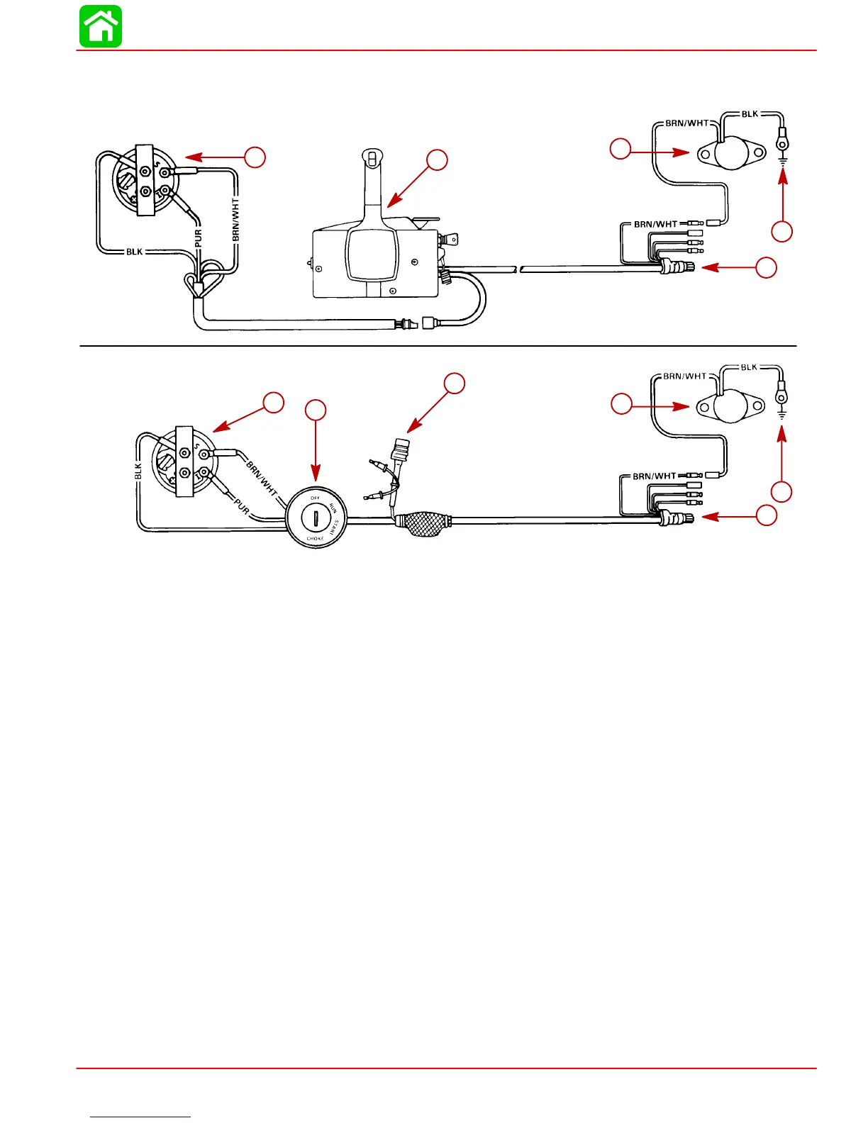
Trim Indicator Wiring Diagrams
22908
Wiring Diagram - For boats equipped with Quicksilver
Commander Series side mount remote control.
Wiring Diagram - For boats equipped with Quicksilver
Ignition/Choke and Main Harness Assembly.
a
b
c
e
d
a
f
g
c
e
d
a-Trim Indicator
b-Remote Control
c-Trim Sender
d-Engine Ground
e-To Engine
f-Ignition Switch
g-Power Trim Harness


 To Next Page