CV610-U3-V2 Manual
www.marshall-usa.com 6
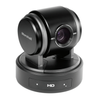
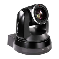
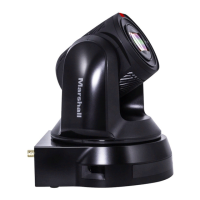
4. Camera Diagrams
1. 12V DC Power Port
Connect the supplied AC power adaptor and cord.
2. Extension Module Port
Composite port for extra features to provide RS-232, RS-422/RS-485, CVBS, HDMI, Audio Line
functionalities
3. USB 3.0 and USB2.0 Port
Outputs the images from this unit as a USB3.0 and USB2.0 video signal.
Do not apply the voltage higher than the rated value to the USB terminal.
This unit does not have the Battery Charging function. This unit supports USB2.0 and USB3.1.
This unit does not support the USB suspend.
4. IR Remote Controller Sensors
These are sensors to receive commands from infrared remote controller.
5. Power LED Indicator
Turns green when the camera is connected to power outlet. When the power is turned on, it
takes about 15 to 30 seconds to display the image after LED turns on.
6. Lens
This is a 10X magnification optical zoom lens.
7. Communication LED Indicator
Flashes orange when the camera receives commands from the infrared remote controller.
8. MIC
Built-in microphone. Range of sensitivity is within 15 feet.
9. Bottom DIP Switch
Used for setting the camera configuration.
For details, refer to the Bottom DIP Switch Se¬ttings (page 18).
10.Fix mounting holes
11.Tripod mounting holes
4.1 Camera