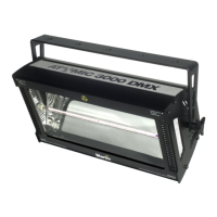
Atomic 3000 user manual Atomic 3000 specifications 25
A
TOMIC
3000
SPECIFICATIONS
B
PHYSICAL
Size (without bracket): . . . . . . . . . . . . . . . . . . .245 x 425 x 240 mm (9.7 x 16.7 x 9.5 in)
Weight: . . . . . . . . . . . . . . . . . . . . . . . . . . . . . . . . . . . . . . . . . . . . . . . . . . . 7.5 kg (16.5 lb)
THERMAL
Maximum ambient temperature: . . . . . . . . . . . . . . . . . . . . . . . . . . . . . . . . . 40° C (104° F)
CONTROL AND PROGRAMMING
DMX-512 (1990) control: . . . . . . . . . . . . . . . . . . . . . . . . . . . . 1, 3, and 4 channel modes
Data pinout: . . . . . . . . . . . . . . . . . 3-pin XLR - pin 1 shield, pin 2 cold (-), pin 3 hot (+)
Compatible remote controls:. . . . . . . . . . . . . . . . . . . . . . . . . Martin MC-1 and Detonator
Stand-alone control: . . . . . . . . . . . . . . . . . . . . . . . . . . . . . .via N.O. or N.C. SPST switch
Stand-alone options: . . . . . . . . . . . . . . . . . . . . . . . . .selectable flash rate or blinder effect
APPROVED LAMPS
MAX-15 Strobe lamp, Xenon (200-250 V supply). . . . . . . . . . . . . . . . . . . P/N 97010307
MAX-7 Strobe lamp, Xenon (90-120 V supply). . . . . . . . . . . . . . . . . . . . . P/N 97010308
Philips XOP 15-OF (200-250 V supply). . . . . . . . . . . . . . . . . . . . . . . . . . . P/N 97010305
Philips XOP 7-OF (90-120 V supply). . . . . . . . . . . . . . . . . . . . . . . . . . . . . P/N 97010306
AC SUPPLY
AC input: . . . . . . . . . . . . . . . . . . . . . . . . . . . . . . . . . . . . . . . . . . . . 2.5 mm
2
trailing cable
Approved AC voltage and frequency range (MAX-7 model): . . . . 90 - 120V, 50 - 60 Hz
Approved AC voltage and frequency range (MAX-15 model): . . 200 - 250 V, 50 - 60 Hz
Peak current consumption: . . . . . . . . . . . . . . . . . . . . . . . . . . . . . . . . . . . . . . . . . . . . .33 A
Typical current consumption (MAX-15, high power mode). . . . . . . . . . . . . . . . . . . . .8 A
FUSES
Primary fuse: . . . . . . . . . . . . . . . . . . . . . . . . . . . . . . . . . . 20 AT / 250 V, P/N 05020040
CONSTRUCTION
Housing: . . . . . . . . . . . . . . . . . . . . . . . . . . . . . . . . . . . . . . . . . . . . . . . . . . . . . . . . . . . steel
Finish: . . . . . . . . . . . . . . . . . . . . . . . . . . . . . . . . . . . . . . . . . . electrostatic powder coating
INSTALLATION
Minimum distance to combustible materials: . . . . . . . . . . . . . . . . . . . . . . . 0.5 m (20 in)
Minimum distance to illuminated surfaces: . . . . . . . . . . . . . . . . . . . . . . . . . . .1 m (39 in)
Minimum clearance around fan and air vents: . . . . . . . . . . . . . . . . . . . . . . . . 0.1 m (4 in)