12
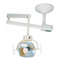
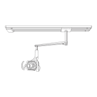
Ceiling Light Installation Instructions
Although traditional methods dictate mounting the light to the left side of the chair for a right-handed
operator and vice-versa for left-handed, careful consideration should be given to mounting location,
especially to prevent interference with x-ray units. Also consider which side of the chair the patient enters.
The light will function and position the same regardless of which side of the chair it is mounted on.
Evaluate the construction of the ceiling. See included drawings for suggestions on the best support
method to use, based on whether you have a conventional or suspended ceiling.
1. Refer to gure #2 for proper location of the ceiling light in relation to the dental chair.
2. After the required support structure is in place, locate and remove from the shipping box the following
items:
A. Ceiling mounting plate
B. Ceiling post
C. Installation hardware kit
3. Attach the ceiling mount plate to the support structure using the supplied lag screws or other appropriate
hardware as dictated by support method employed. Be certain that the hardware employed can withstand
a force of 75 lbs. at each attachment point.
4. Route the power cord through the ceiling post and slip the post into the socket on the ceiling plate. Align
the retainer bolt holes in the post with the holes in the post socket and install the retainer bolt. Tighten
rmly. (See gure 9).
5. Level the post front to back. Move the level 90 degrees and repeat the above procedure with the remain-
ing screws for leveling side to side. Recheck level in both directions; then fully tighten all leveling screws (
A magnetic level works best).
6. Turn the power to the ceiling light circuit off and make the necessary electrical connections. We recom-
mend that a licensed electrician make the required power connections (See gures 9 & 10).
7. Place the mounting plate cover halfway up the ceiling post with the cover retaining collar below it. Lightly
tighten the setscrew to temporarily hold the cover in position. CAUTION: Do not overtighten the set screw.
It will mark the painted post.
8. Place the locking tab retaining collar on the post just above the locking tab slot and lightly tighten the set
screw (See cautionary note in Step 7). Install the stop screw in the light adapter according to which side
of the chair the light is mounted on. (See gure 10).
9. Grease the light adapter and the inside of the bottom of the ceiling post using supplied lubricant. Have an
assistant hold the light assembly with the adapter near the bottom of the ceiling post. Plug the short male
cord into the female coiled cord rmly, being certain that this plug makes a tight connection so as not to
become disconnected in the future.
10. Slide the light adapter into the bottom of the ceiling post until it bottoms. Look into the slot to be sure the
stop screw is not within the connes of the slot. Now place the locking tab into the slot in the side of the
ceiling post. (See gure 10). The locking tab ts ush into the ceiling post. Now loosen the set screw on
the locking tab retaining collar and lower it over the slot. Align the collar with the bottom of the post and
tighten the set screw rmly. The assistant supporting the light can now release it.