- 10 -
MC-HTS(Hedge Trimmer Attachment)
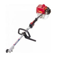
Installing Shaft and Gearcase
Attach the driveshaft tube assembly to the Hedge Trimmer gearcase assembly.
Note: Carefully inspect both ends of the drive shaft protruding
from the drive shaft tube. The squared end of the drive
shaft positions toward the connector of the power unit.
The splined end of the drive shaft connector to the
gearcase assembly while rotating the drive shaft to engage
the splines. Align the locating holes and install the locating
screw through the side of the gearcase. Then tighten the clamping
screws. If properly installed, rotating the square end of the drive
shaft will cause the trimmer blades to move.
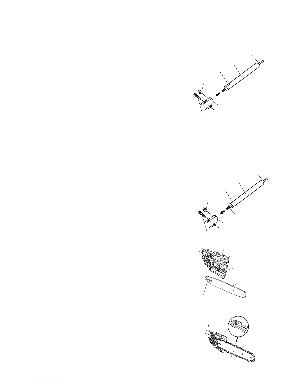
MC-PS (Pruner Attachment)
Installing Shaft and Gearcase
Attach the driveshaft tube assembly to the Hedge Trimmer
gearcase assembly.
Note: Carefully inspect both ends of the drive shaft protruding
from the drive shaft tube. The squared end of the drive
shaft positions toward the connector of the power unit.
The splined end of the drive shaft connector to the
gearcase assembly while rotating the drive shaft to engage
the splines. Align the locating holes and install the locating
screw through the side of the gearcase. Then tighten the clamping
screws. If properly installed, rotating the square end of the drive
shaft will cause the trimmer blades to move.
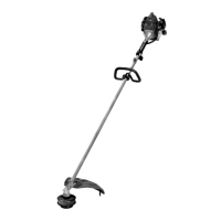
Installing Guide Bar and Chain
1. Remove the nuts from the two bar studs.
2. Fit the guide bar over the two bar studs. Do not engage the
chain tensioner adjustment pin hole at this time.
3. place the chain over the rim sprocket and into the groove on
the guide bar. Make sure the cutting teeth edges are facing
forward on the top side of the guide bar.
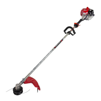
4. Pull the guide bar forward until the chain tensioner adjustment
pin hole is positioned over the chain tensioner adjustment pin.
If necessary, turn the chain tensioner screw in the appropriate
direction to align the pin with the hole. Check that the drive links
on the chain fit correctly into the rim sprocket and guide bar
groove.
S