7
Masimo
www.masimo.com
6
Masimo
www.masimo.com
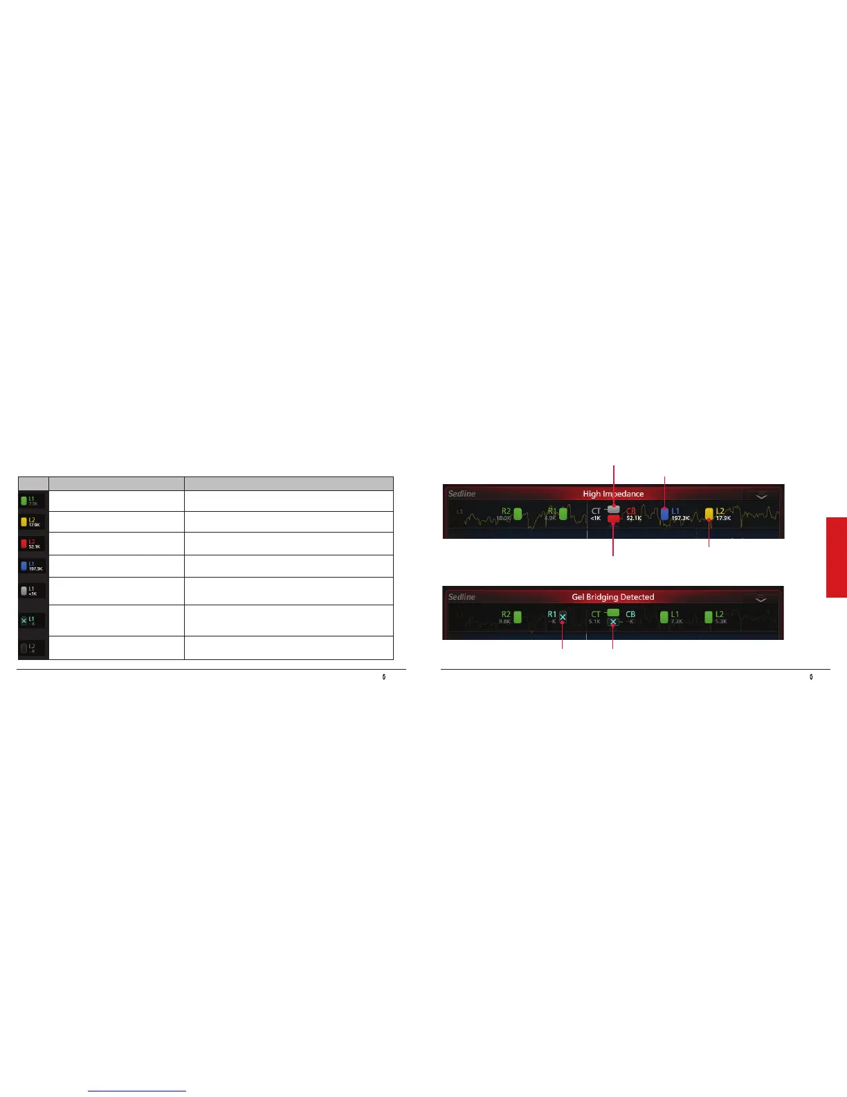
Electrode Status Display
Electrode Status Display
Electrode Status Examples
The electrode status display provides the sensor’s electrode conductance status.
Display Description Action
Green - Electrode impedance is within
acceptable range.
No electrode adjustment necessary.
Yellow - Electrode impedance is marginal
but acceptable.
Minor electrode adjustment may be required.
Red - Electrode impedance is out of
acceptable range.
1. Gently push/wiggle electrodes until all are yellow and/or green.
2. Re-prepping of electrodes may be necessary.
Blue - Unreliable connection or
disconnection of Sensor electrodes.
Conrm that all sensor electrodes, particularly electrodes CT and
CB, are properly connected.
Light Gray - Impedance values are
unavailable because Sensor, Patient Cable,
or Module is not adequately detected.
1. Replace the Patient Cable.
2. The Module may need to be replaced.
Dark Gray with a Cyan “X” - Gel-bridging
detected on the electrode.
1. Clean any gel that has leaked outside of the electrodes on the
patient's forehead.
2. Conrm that all sensor electrodes are properly connected.
3. The Sensor may need to be replaced.
Dark Gray - Electrode monitoring
disabled. All electrode icons will be dark
gray.
1. Conrm that Sensor is plugged into Patient Cable.
2. Conrm that Patient Cable is connected to Module.
Gel-bridging between R1 and CB
Impedance Value unavailable on CT
Unreliable connection on L1
Unacceptable impedance on CB
High but acceptable impedance on L2
 Loading...