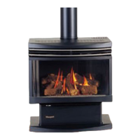
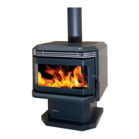
14 F37 Masport Rear Flued Room Sealed Freestanding Gas Heater
INSTALLATION
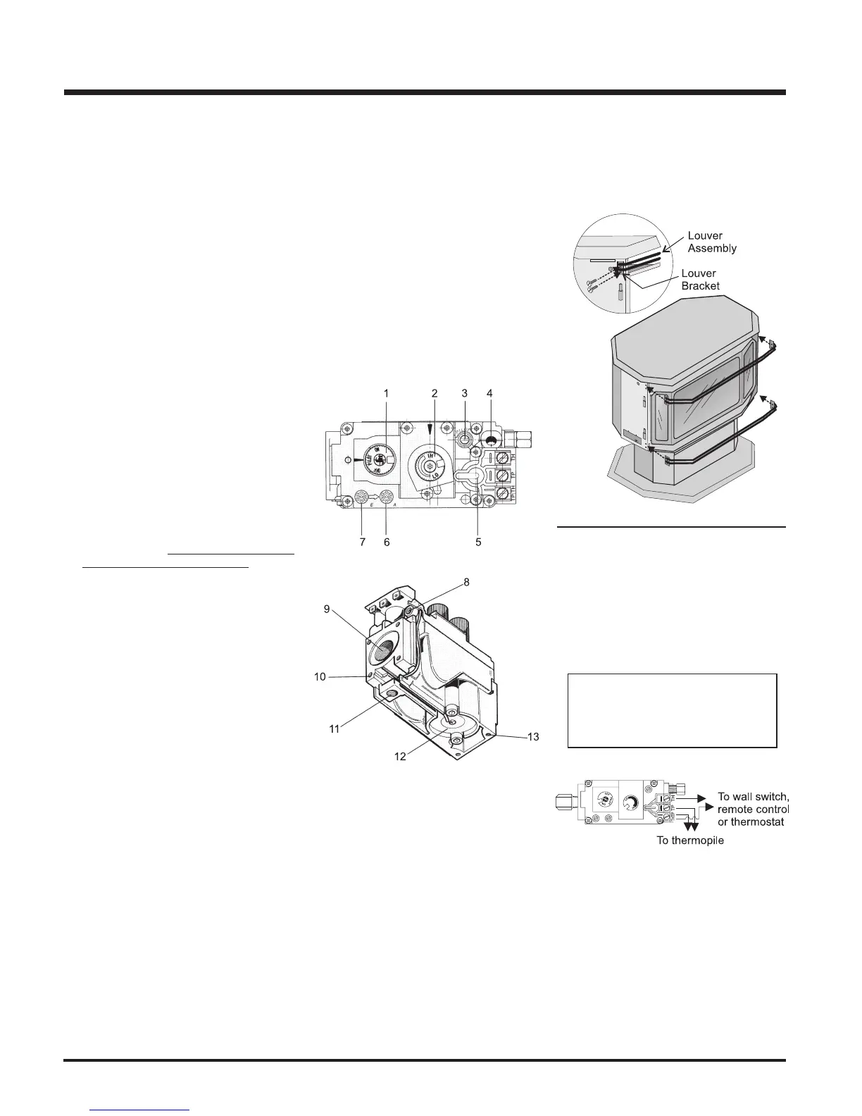
OPTIONAL WALL
THERMOSTAT
A wall thermostat may be installed if desired.
Connect the wires as per the wiring diagrams.
Note that the wires are connected to the "TH"
on the gas valve. Use table below to determine
the maximum wire length:
CAUTION
Do not connect the millivolt
wall thermostat wires
to the 240V wires.
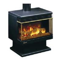
LOUVRE
INSTALLATION
Attach the top & bottom louvres to the side stove
panel using 2 screws per side.
PRESSURE TESTING
The manifold pressure is controlled by a regu-
lator built into the gas control, and should be
checked at the pressure test point.
Note: To properly check gas pressure,
both inlet and manifold pressures
should be checked using the valve
pressure ports on the valve.
1) Make sure the valve is in the "OFF" position.
2) Loosen the "IN" and/or "OUT" pressure
tap(s), turning counterclockwise with a 1/
8" wide flat screwdriver.
3) Attach manometer to "IN" and/or "OUT"
pressure tap(s) using a 5/16" ID hose.
4) Light the pilot and turn the valve to "ON"
position. Read manometer.
5) The pressure check should be carried out
with the unit burning and the setting should
be within the limits specified on the safety
label.
6) When finished reading manometer, turn off
the gas valve, disconnect the hose and
tighten the screw (clockwise) with a 1/8"
flat screwdriver. Note: Screw should be
snug, but do not over tighten
Valve Description
1) Gas cock knob
2) Manual high/low adjustment
3) Pilot Adjustment
4) Thermocouple Connection
5) Main Operator
6) Outlet Pressure Tap (Manifold Pressure)
7) Inlet Pressure Tap (Supply Pressure)
8) Pilot Outlet
9) Main Gas Outlet
10)Flange Securing Screw Holes
11)Alternative TC Connection Point
12)Thermoelectric Unit
13)Additional Valve Mounting Hole
 Loading...