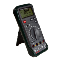
1.
2.
3.
Connect the black test lead to the COM jack and the red test lead to the V/Ω
jack. (NOTE: The polarity of red test lead connection is positive “+”)
Set the function switch at
position and push the Ω/ button.
Connect test leads to two points of the circuit under measurement. If continuity
exists (i.e., the resistance is lower than 30Ω), built-in buzzer will sound.
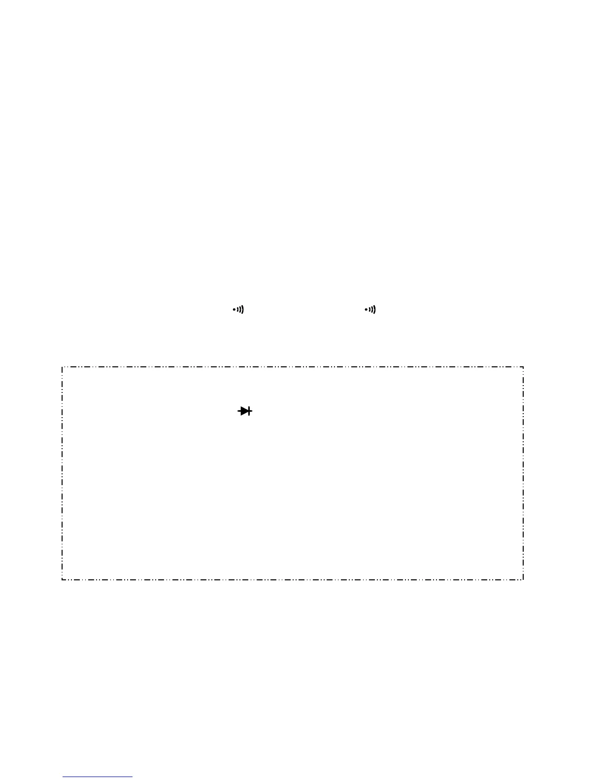
3.7 DIODE TESTING
1. Connect the black test lead to the COM jack and the red test lead to the V/Ω
jack.
-14-
2.
3.
(NOTE: The polarity of the red test lead connection is positive “+” )
Set the function switch at
position.
Connect the red test lead to the anode of the diode to be tested and the black
test lead to the cathode.