WARNING!
For safety reasons Ground Fault Circuit Interrupters (GFCIs), also known as Residual
Current Devices (RCDs), of 30mA must be integrated in the AC input and AC output of the
CombiMaster Inverter/Charger. Refer to locally applicable regulations regarding grounding
of autonomous power systems.
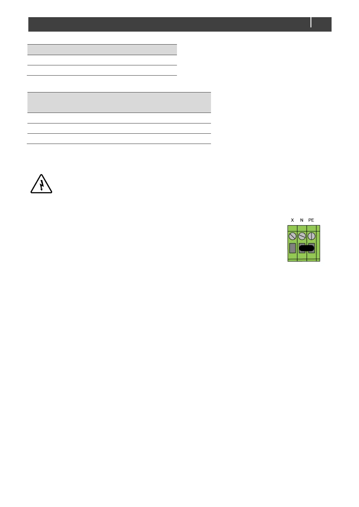
Neutral to Ground Bonding
To ensure a correct operation of Ground Fault Circuit Interrupters (GFCIs), the
grounding system jumper (located on the left side of the CombiMaster
Inverter/Charger) must be placed between N and PE. Then the Neutral (N) output
is automatically connected to the Safety Ground (PE / GND) if the AC input of the
CombiMaster Inverter/Charger is disconnected from an external AC source.
4.5.4 Network wiring (CZone/MasterBus)
The CombiMaster Inverter/Charger can be connected to a CZone or MasterBus network. For CZone,
use an RJ45 Drop cable CZone/MB. For MasterBus, use a MasterBus cable and daisy chain the
CombiMaster Inverter/Charger to the other devices. Both networks need a terminating device on both
ends of the network. Do not make ring networks. For more details on networks, please contact your
Mastervolt supplier.
4.6 Things you need
Make sure you have all the parts you need to install a CombiMaster Inverter/Charger:
• CombiMaster Inverter/Charger (included).
• Battery temperature sensor with cable and plug (included).
• For CZone setup, an RJ45-M12 Drop cable CZone/MB (included) and a tee connector (not
included).
• For MasterBus setup, an RJ45 MasterBus cable (not included).
• DC cables to connect the CombiMaster Inverter/Charger to the batteries and common negative. See
section 4.5.1 for specifications.
• DC fuse holder with a DC fuse, to be integrated in the positive DC cable (as per ABYC
recommendations).
• Screws/bolts (Ø ¼" / 6mm) with plugs to mount the CombiMaster Inverter/Charger to a surface. Use
mounting materials which are suited to carry the weight of the CombiMaster Inverter/Charger.