CombiMaster 120V Series – User and Installation Manual
Step 11. Option: Connect the CombiMaster Inverter/Charger to the CZone or MasterBus network. See
section 4.9 for more information on system integration.
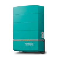
Adding the CombiMaster
Inverter/Charger to a CZone
network
1 Disconnect the backbone at the
closest backbone connection and
add in a tee connector.
2 Reconnect the backbone
connection(s) with the new tee
connector in place.
3 Connect the RJ45 CZone/MB
drop cable to the black coupler on
the tee and then connect to the
CombiMaster Inverter/Charger.
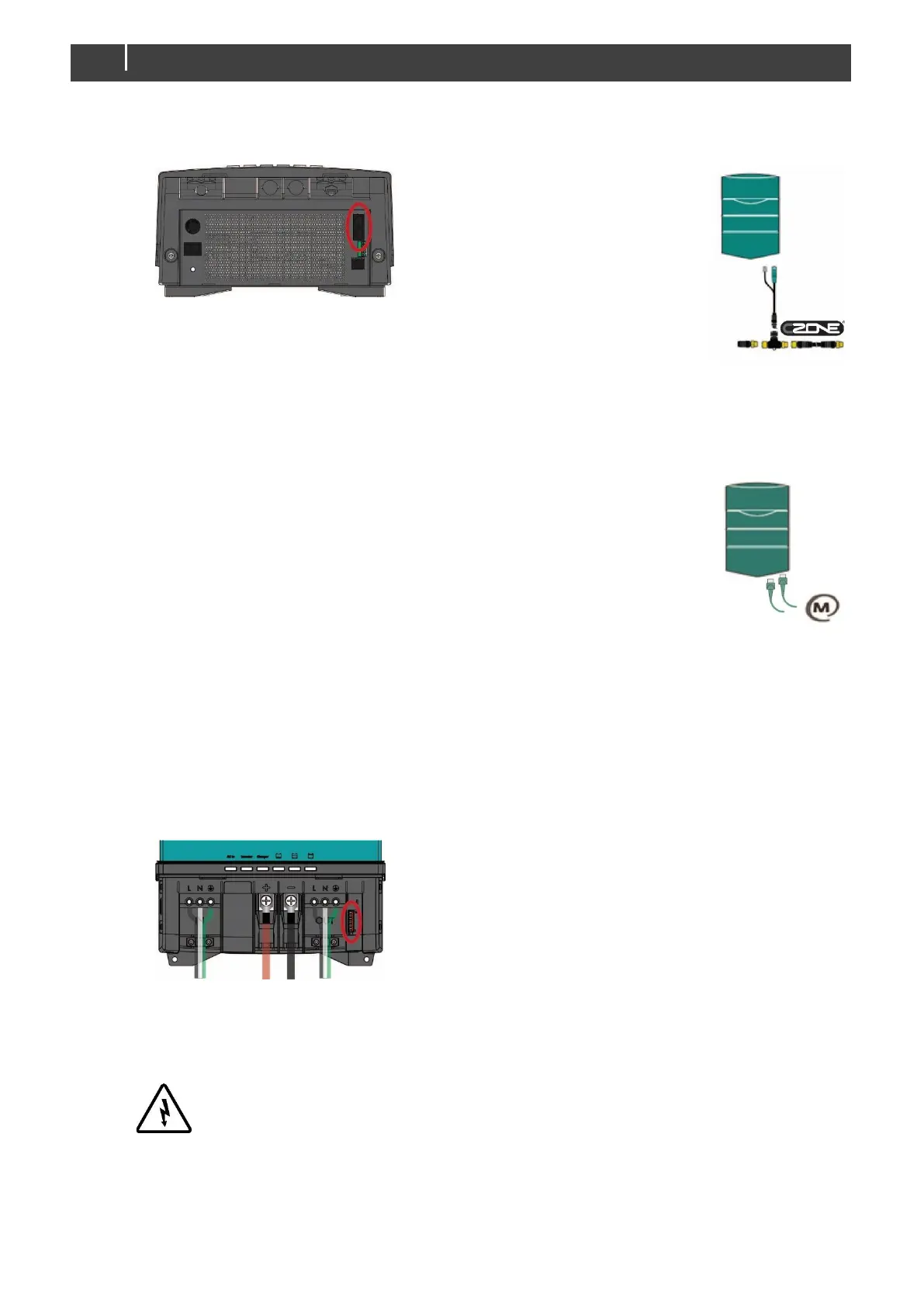
Adding the CombiMaster
Inverter/Charger to a MasterBus
network
1 Disconnect a MasterBus cable or
Terminator from the closest
MasterBus device and connect it
to the CombiMaster
Inverter/Charger.
2 Connect the new MasterBus cable
to the other MasterBus device and
then connect to the CombiMaster
Inverter/Charger.
Ensure that the network is properly
terminated.
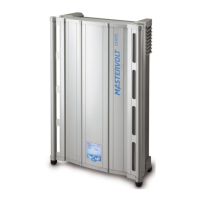
Step 12. Option: use a small screw driver to change DIP switch settings. See section 5.1 on page 19.
Note: if added to a CZone network, the DIP switches are
used to set the CZone address during configuration.
Step 13. Option: connect external alarm or remote switch input. See section 4.8.
Step 14. Set the desired output voltage and other configuration settings using a remote control panel
or the DIP switches, see chapter 5 on page 19.
Step 15. Check all wiring. If all wiring is OK: Place the inverter fuse.
WARNING!
When the fuse is placed, internal capacitors may cause a spark. This is normal
Step 16. Close the connection compartment and fix the screws at the bottom.
Step 17. Switch on the CombiMaster Inverter/Charger.