INSTALLATION
20 January 2015 / Mass Combi 12/1600-60; 12/2200-100; 24/1800-35; 24/2600-60 / EN
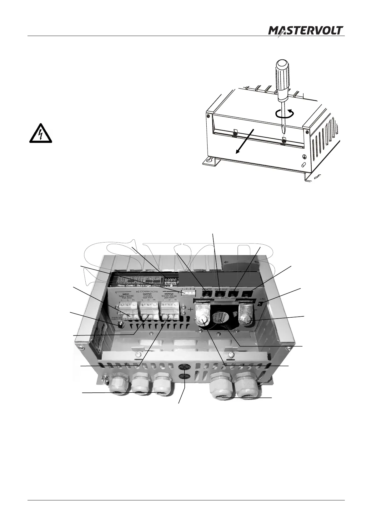
5.5 REMOVAL OF THE FRONT PANEL
See figure 21. Steps:
1 Loosen the two Phillips screws that secure the front
cover plate for two turns.
2 Slide the front cover plate from the cabinet
(downwards).
The connectors for the battery, the AC and the remote
panel are now visible. See figure 22
WARNING
The front panel may never be removed while
the Mass Combi is still connected to a power
source!
Figure 21
5.6 OVERVIEW CONNECTION COMPARTMENT
Figure 22: Overview connection compartment
Thermal fuse
Negative
battery
terminal
AC input
AC output
POWER
AC output
SHORT BREAK
Positive battery
terminal
Cooling fan
Second 5A
charger
output
Remote
connection
(ICC panel)
Connector for
temperature
sensor
QRS232
connector
DIP-switches
PARALLEL
connector
Alarm
contacts
Cable glands
for AC wiring
Cable glands for
main DC wiring
Grommets for wiring of remote panels
Step 1
2x
Step 2

 Loading...


