INSTALLATION
EN / Mass Combi 12/1600-60; 12/2200-100; 24/1800-35; 24/2600-60 / January 2015 23
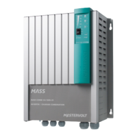
5.8.1 Wiring instructions for one Mass Combi
(stand alone operation)
See figure 24.
1 See reference . Connect the external AC-source to
the AC-input of the Mass Combi. Integrate a fuse
(value depending on the used wire diameter with a
maximum of 50Amps) and a Residual Current Device
(RCD) into this wiring.
2 See reference . Connect the AC-output POWER of
the Mass Combi to the power distribution group.
3 See reference . Connect the output SHORT BREAK
of the Mass Combi to the SHORT BREAK distribution
group. Integrate a Residual Current Device (RCD)
into this wiring.
4 See reference . Run the DC-cables between the
DC-distribution and the Mass Combi. Connect the red
cable to the plus (+) connection, the black cable to the
minus (–) connection. Do not install the DC-fuse of the
DC-distribution before the entire installation is
completed (see chapter 7).
5 See reference . Attach the temperature sensor to
the battery and run the cable into the Mass Combi.
Link the RJ12 connector to the “TEMP.SENS”-
connector (Data Bus Connections).
6 Option: if you want to make use of the possibility to
give a maintenance charge to a small battery set (like
a starter battery), run a 6mm² /AWG10 red cable with
a fuse holder between the positive pole of the starter
battery and Mass Combi. See reference . Fix the
cable with an insulated faston to the “+5A”-
connection. Integrate a 25 Amps–T fuse in this wire.
The negative pole of this battery must be connected
to the negative pole of the service battery.
Continue with section 5.8.3
 Loading...
