INSTALLATION
26 January 2015 / Mass Combi 12/1600-60; 12/2200-100; 24/1800-35; 24/2600-60 / EN
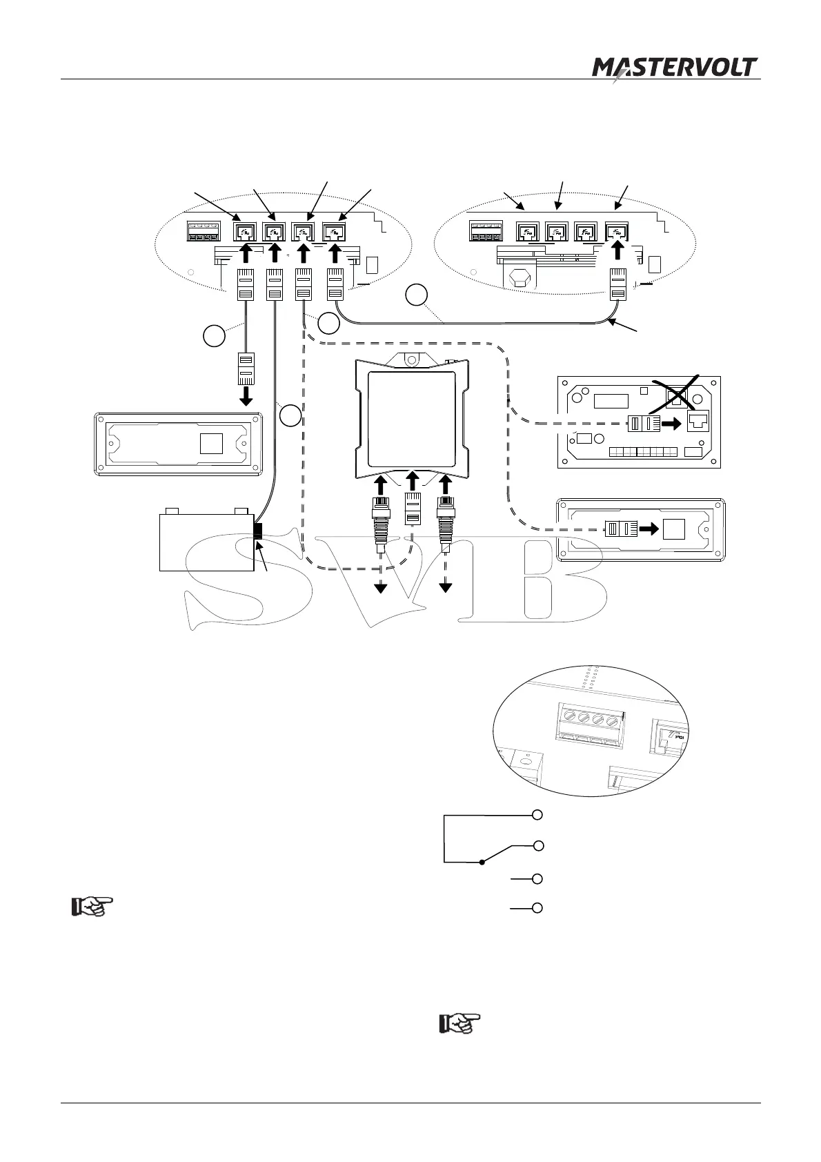
5.8.3 Interfacing (optional)
1 See figure 26, reference . If you want to install the
ICC remote control panel, run the communication
cable between Mass Combi A and the panel. Connect
the RJ12 connector to the “REMOTE”-input (Data Bus
Connections) of Mass Combi A.
2 The MasterBus – Combi interface or other panels
than the ICC remote control panel must be connected
to the “QRS232”-connection; reference . Refer to
the applicable installation manual for detailed
instructions.
NOTE
When using a Masterlink MICC remote panel:
See section 6.2.5 for DIP-switch setting at the
Mass Combi;
See section 4.4 of the user’s manual of the
Masterlink MICC to enable the Mass Combi
setting.
3 See Figure 27. The alarm contact is switched to
“Normally Open” in case of an alarm situation, see
section 3.6. Maximum switching current: 1 Amp.
5.9 SETTINGS
Continue with chapter 6 for DIP-switch
settings
1
-
2
-
3
-
4
1 (C) Common
2 (NC) Normally Closed
3 (NO) Normally Open
4 Not used
Figure 27: alarm contact
Figure 26:
Connection of remote control panels, battery temperature sensors and communication cable for parallel operation
APC panel (optional)
Masterlink MICC (optional)
MasterBus –
Combi interface
M A STERBUSREMOTE QRS232
+5A
NEG
TE M P. SENS
BATTERY
1 - 2 - 3 - 4
PO S
+
M A STERBUSREMOTE QRS232
+5A
NEG
TE M P. SENS
BATTERY
1 - 2 - 3 - 4
PO S
+
ICC panel (optional)
+ –
Service
Batteries
Temperature sensor
Communication
cable for parallel
operation
5
8
9
6
Mass Combi “A”
(Master or stand alone)
Mass Combi “B”
(Slave)
Remote
connection
(ICC panel)
Connector for
temperature
senso
QRS232
connection
PARALLEL
connection
Remote
connection
(ICC panel)
PARALLEL
connection
Connector for
temperature
senso
MasterBus
network

 Loading...


