54 Appendix B: Technical information
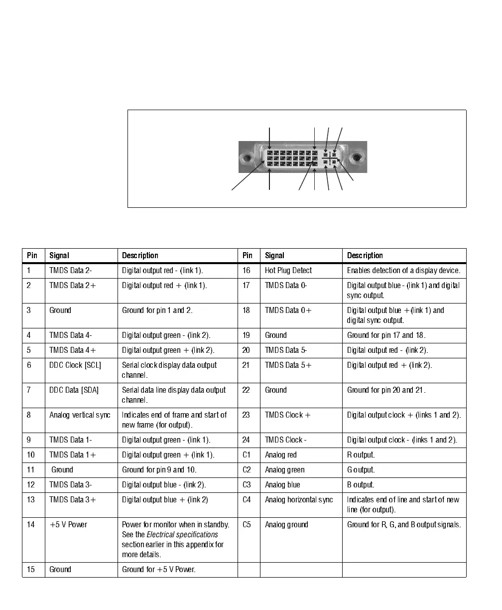
DVI-I connectors 1/5 and 2/6 (multi-format output)
DVI-I connectors 1/5 and 2/6 are output connectors. A DVI-I connector is shown
in the following image:
The pin assignment for output DVI-I connectors 1/5 and 2/6 is as follows:
C2C1
C4C3
8
24
1
17
9
16
C5
Pin Signal Description Pin Signal Description
1 TMDS Data 2- Digital output red - (link 1). 16 Hot Plug Detect Enables detection of a display device.
2 TMDS Data 2+ Digital ou tput r ed + (link 1). 17 TMDS Data 0- Digital output blue - ( link 1) an d di gital
sync output.
3 Ground Ground for pin 1 and 2. 18 TMDS Data 0+ Digital output blue +(link 1) and
digital sync output.
4 TMD S Data 4- Digital out put green - (l ink 2). 19 Ground Ground for pin 17 and 18 .
5 TMDS Data 4+ Digital output green + (link 2). 20 TMDS Data 5- Digital output red - (link 2).
6 DDC Clock [SCL] Serial clock display data output
channel.
21 TMDS Data 5+ Digital output red + (link 2).
7 DDC Data [SDA] Serial data line display data output
channel.
22 Ground Ground for pin 20 and 21.
8 Analog vertical sync Indicates end of frame and start of
new frame (for output).
23 TMDS Clock + Digital output clock + (links 1 and 2).
9 TMDS Data 1- Digital output green - (link 1). 24 TMDS Clock - Digital output clock - (links 1 and 2).
10 TMDS Data 1+ Digital output green + (link 1). C1 Analog red R output.
11 Ground Ground for pin 9 and 10. C2 Analog green G output.
12 TMDS Data 3- Digital output blue - (link 2). C3 Analog blue B output.
13 TMDS Data 3+ Digital output blue + (link 2) C4 Analog horizontal sync Indicates end of line and start of new
line (for output).
14 +5 V Power Power for monitor when in standby.
Se e th e
Electrical specifications
section earlier in this appendix for
more details.
C5 Analog ground Ground for R, G, and B output signals.
15 Ground Ground for +5 V Power.