Connectors on Matrox Orion HD boards 55
DVI-I connectors 3/7 and 4/8 (multi-format input)
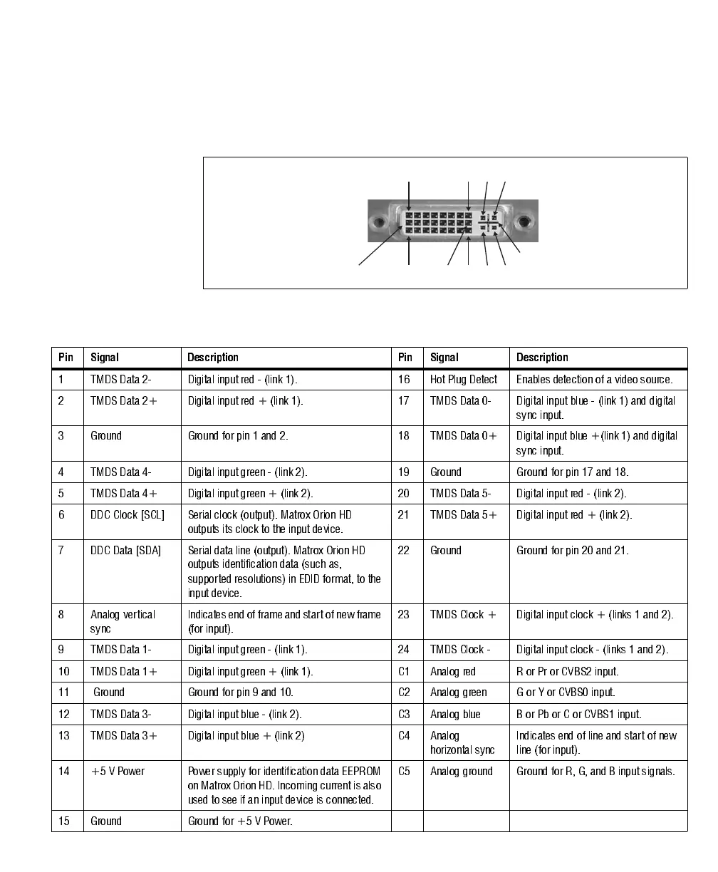
DVI-I connectors 3/7 and 4/8 are input connectors. A DVI-I connector is shown
in the following image:
The pin assignment for input DVI-I connectors 3/7 and 4/8 is as follows:
C2C1
C4C3
8
24
1
17
9
16
C5
Pin Signal Description Pin Signal Description
1 TMDS Data 2- Digital input red - (link 1). 16 Hot Plug Detect Enables detection of a video source.
2 TMDS Data 2+ Digital input red + (link 1). 17 TMDS Data 0- Digital input blue - (link 1) and digital
sync input.
3 Ground Ground for pin 1 and 2. 18 TMDS Data 0+ Digital input blue +(link 1) and digital
sync input.
4 TMDS Data 4- Digital input green - (link 2). 19 Ground Ground for pin 17 and 18.
5 TMDS Data 4+ Digital input green + (link 2). 20 TMDS Data 5- Digital input red - (link 2).
6 DDC Clock [SCL] Serial clock (output). Matrox Orion HD
outputs its clock to the input device.
21 TM DS Data 5 + D igital input red + (link 2).
7 DDC Data [SDA] Serial data line (output). Matrox Orion HD
outputs identification data (such as,
supported resolutions) in EDID format, to the
input device.
22 Ground Ground for pin 20 and 21.
8 Analog vertical
sync
Indicates e nd of f rame and s tart of new fr ame
(for input).
23 TMDS Clock + Digital input clock + (links 1 and 2).
9 TMDS Data 1- Digital input green - (link 1). 24 TMDS Clock - Digital input clock - (links 1 and 2).
10 TMDS Data 1+ Digital input green + (link 1). C1 Analog red R or Pr or CVBS2 input.
11 Ground Ground for pin 9 and 10. C2 A nalog green G or Y or CVBS0 input.
12 TMDS Data 3- Digital input blue - (link 2). C3 Analog blue B or Pb or C or CVBS1 input.
13 TMDS Data 3+ Digital input blue + (link 2) C4 Analog
horizontal sync
Indicates end of line and start of new
line (for input).
14 +5 V Power Power supply for identification data EEPROM
on Matrox Orion HD. Incoming current is also
used to see if an input device is connected.
C5 A nalog ground Ground for R, G, and B input signal s.
15 Ground Ground for +5 V Power.