4-4
TI015G0013
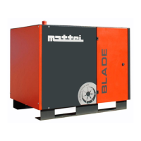
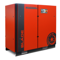
BLADE 1-2-3
DIMENSIONS OF COMPRESSED AIR
DISTRIBUTION PIPINGS
We mention that the main causes for wastes
are pipings with unsuitable diameter and
losses due to an improper setting up of the
equipment or deteriorated materials.
The pipe diameter must be duly selected so
as to minimize the pressure drop between
the compressor or the storage receiver and
the point of use, based on the machine
features, like air delivery and working
pressure.
The pressure drop is proportional to the
pipe length and most losses occur during
the change of direction (curves, elbows) and
in the valves.
With a pipe having the same diameter as the
compressor outlet, the length should not
exceed 50 m.
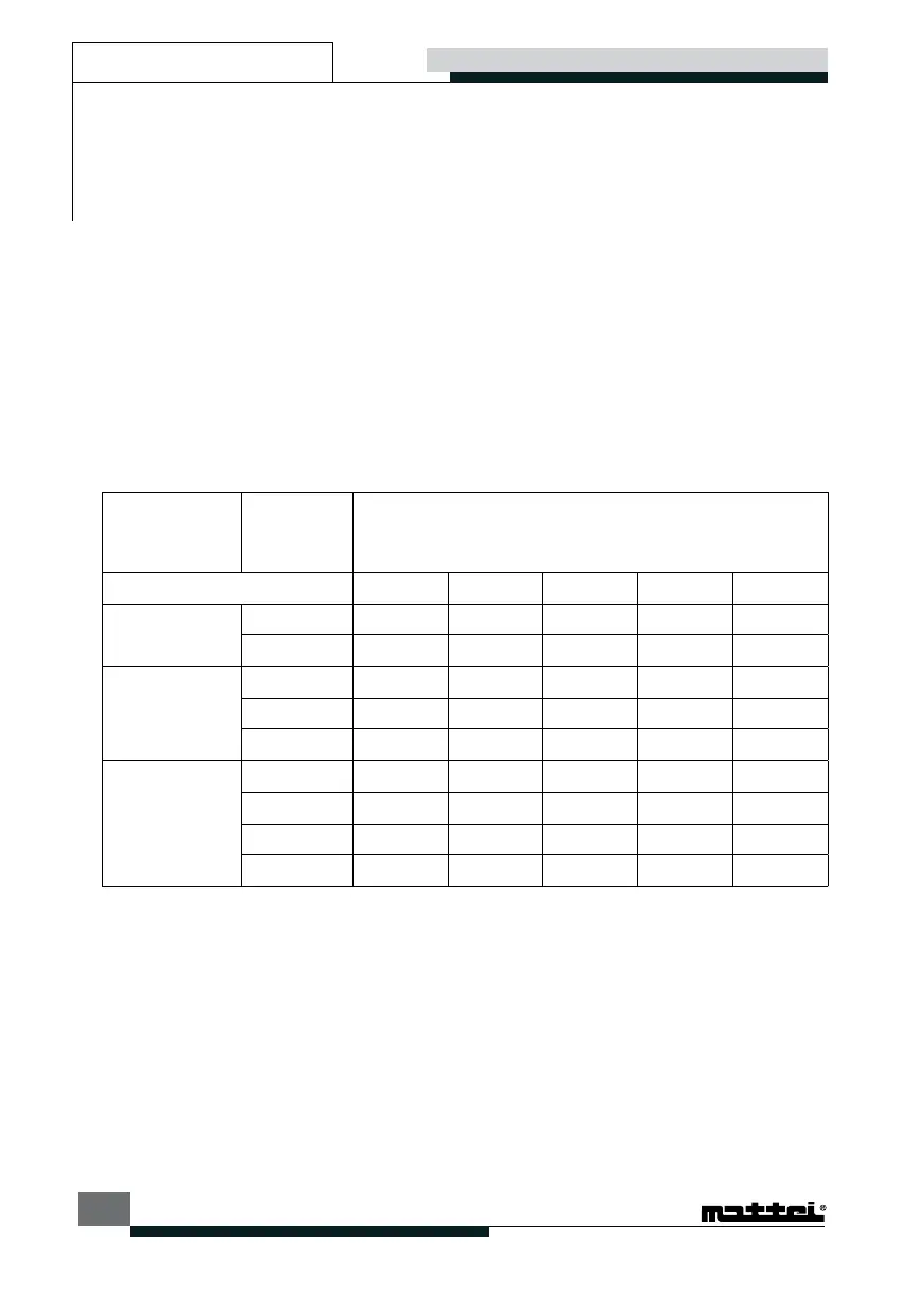
To make a check of one’s own equipment,
“Table 1” gives the load losses, over 10
metres straight piping, according to
nominal diameters usually employed and at
dierent air delivery and working pressure
conditions.
A perfect air distribution system should limit
the pressure drop from compressor to the
point of use within few tenths of bar.
PIPE
DIAMETER “
FREE AIR
DELIVERY
m
3
/min
PRESSURE bar
6 7 8 9 10
3/8
0,125
0,032 0,028 0,025 0,022 0,020
0,25
0,115 0,101 0,090 0,081 0,073
1/2
0,125
0,008 0,007 0,006 0,005 0,005
0,25
0,027 0,024 0,021 0,019 0,017
0,5
0,099 0,086 0,077 0,069 0,063
3/4
0,5
0,013 0,011 0,010 0,009 0,008
0,75
0,027 0,024 0,021 0,019 0,017
1
0,047 0,041 0,036 0,033 0,030
1,25
0,071 0,062 0,055 0,049 0,045
Table 1. Load losses (bar) for 10 m of straight pipeline.
Transportation and handling Installation
 Loading...