i-HP Industrial inverter air/water heat pumps with axial fans
14
7.2 LIFTING AND HANDLING
The handling must be performed by qualified personnel, properly equipped with appropriate equipment to the weight and the
encumbrance of the unit, in compliance with safety regulations of accident preventing.
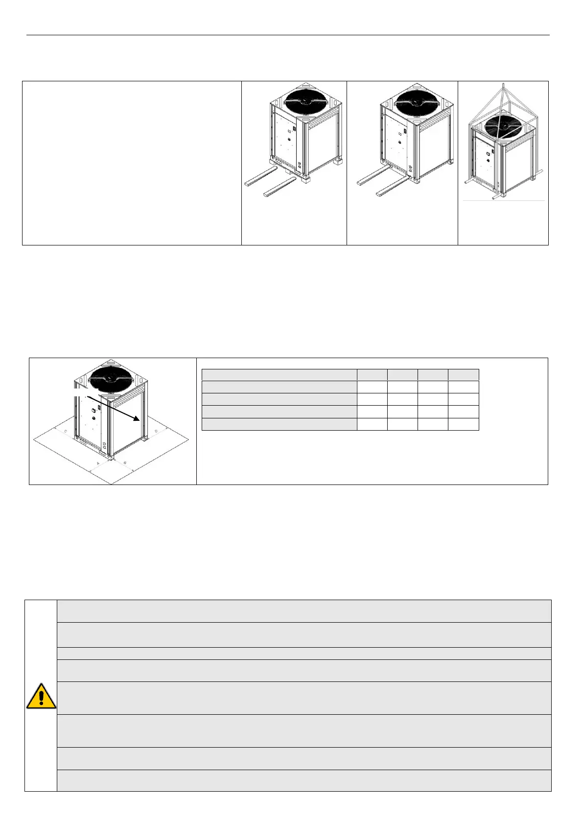
When the unloading and the placement of the unit,
it is highly recommended to avoid any sudden or
violent motion in order to protect the inner
components and the frame. The units can be lifted
by mean of a forklift or, otherwise by mean of belts,
making sure to damage the lateral panels and the
cover of the unit using a structure of spacers as
shown in the drawing. In this context, it is necessary
to hook indirectly the unit to the basement but on
two steel pipes of adequate dimension that to pass
into the appropriate holes situated in the same
basement of the unit. It is important to keep the
unit horizontal during these operations.
1) Handling with forklift
under the pallet
2) Handling with forklift
under the unit using the
appropriate windows of
passing forks
3) Handling by
mean of belts
7.3 LOCATION AND MINIMUM TECHNICAL CLEARANCES
All i-HP models are designed for outdoor installations; any cover over the unit or locating near trees (even if they partially cover
the unit) has to be avoided in order to allow the air recirculation. It is advisable to realize a supporting basement, with adequate
size similar to unit foot-print. The unit vibration level is very low: it is advisable however, to fit a rigid rubber band between
basement and unit base-frame. It is also possible to install anti-vibration supports (springs or rubbers) to keep vibrations at a very
low level. An absolute care has to be taken to ensure adequate air volume to the condenser. The re-circulation of discharge air has
to be avoided; failure to observe this point will result in poor performance or activation of safety controls. For these reasons it is
necessary to observe the following clearances:
i-HP 0250F/i-HP 0250/i-HP-LT 0250
* The recommended minimum distance for installation, maintenance and operation.
N.B. Avoid suspended installations. If you cannot, use your common sense and follow
local regulations, and in the case of doubt, contact your authorized service center.
7.4 HYDRAULIC CONNECTIONS
The hydraulic connections have to be installed in accordance with national and local regulations; pipes can be made up of steel,
galvanized steel or PVC. Pipes have to be designed depending on the nominal water flow and on the hydraulic pressure drops of
the system. All the hydraulic connections must to be insulated with closed-cell material of adequate thickness. Chillers have to be
connected to piping by means of flexible joints. The hydraulic circuit should include the following components:
• Hole thermometers for monitoring the hydraulic circuit’s temperature.
• Manual gate valves to separate the chiller from the hydraulic circuit.
• Y-shaped metallic filter (to be mounted on the return pipe from the plant) with a metallic mesh not larger than 1mm.
• Loading group and discharge valve, where it’s necessary.
WARNING: Make sure that, when designing the pipe length and diameter do not exceed the maximum head loss on
the plant side, please see the technical data given in the table of Paragraph 13 (available head pressure).
WARNING: In the models of i-HP series, the expansion vessel is not integrated on the plant side. The actual capacity of
plant circuit should be checked by the installer in order to provide an expansion tank with adequate volume.
WARNING: Connect the pipes to the attacks by using always key against key system.
WARNING: Unit water inlet pipe have to be in correspondence with the connection labelled: ”WATER INLET”, otherwise
the evaporator may freeze.
WARNING: It is compulsory to install on the WATER INLET connection a metallic filter with a mesh not larger than 1mm.
Should the water flow switch be altered or should the filter not be installed, the warranty will no longer be valid. The
filter have to be kept clean, so make sure it is clean after the unit has been installed, and then check it periodically.
All units are standard supplied with the water flow switch (factory installed). Should the water flow switch be altered,
removed, or should the water filter not be installed on the unit, the warranty will be invalidated. Please refer to the
wiring diagram for the water flow switch electric connections.
The water on the charging/topping up pipe must be opportunely pre-filtered from any suspended particles and
impurities through the use cartridge filter (washable, wrapped wire, etc.) of at least 100 microns.
Check the water hardness with which you load and top up the plant circuit. With particularly hard water, in this case it
is necessary to utilize a water softener. For treating water for the plant, please refer to UNI 8065.



 To Next Page