EasyManua.ls Logo

MAXA i-HP 0270 - AVAILABLE HEAD PRESSURE OF THE UNIT WITH INTEGRATED CIRCULATOR

MAXA i-HP 0270
40 pages
Print Icon
To Next Page IconTo Next Page
To Previous Page IconTo Previous Page
Loading...
i-HP Industrial inverter air/water heat pumps with axial fans
26
13.3 A-WEIGHTED SOUND POWER
Toltal L
w
dB(A)
Octave bands L
W
dB(A)
Size
Fitting out
LW(A)
63 Hz
125 Hz
250 Hz
500 Hz
1.000 Hz
2.000 Hz
4.000 Hz
8.000 Hz
0125
Standard
70,1
46,8
56,5
60,9
64,0
64,5
62,8
56,9
58,1
0125
SL
68,3
44,9
54,3
59,9
62,0
62,3
59,7
58,9
57,5
0125
SSL
67,4
44,0
55,2
58,5
60,9
61,2
58,1
58,2
57,4
0135
Standard
73,6
48,2
57,8
65,0
67,4
67,6
66,7
63,1
59,3
0135
SL
71,8
47,4
57,0
64,0
66,4
66,0
63,5
59,3
58,0
0135
SSL
70,9
45,9
56,8
63,5
65,3
64,9
62,6
58,4
57,9
0250F/0250
Standard
76,5
56,3
60,1
68,1
69,8
70,0
69,8
68,1
60,5
0250F/0250
SL
74,5
56,0
59,7
67,1
68,5
68,3
66,7
64,2
59,2
0250F/0250
SSL
73,6
54,2
59,5
66,3
67,5
67,3
65,4
63,4
59,1
0260
Standard
78,3
61,3
66,1
71,1
71,8
71,0
70,8
69,1
61,5
0260
SL
76,5
61,0
65,7
70,1
70,5
69,3
67,7
65,2
60,2
0260
SSL
75,6
59,2
65,5
69,3
69,5
68,3
66,4
64,4
60,1
0270
Standard
78,9
62,3
67,1
72,0
72,3
71,4
71,3
69,6
62,0
0270
SL
77,1
62,0
66,7
71,0
71,0
69,7
68,2
65,7
60,7
0270
SSL
76,3
60,2
66,5
70,3
70,0
68,7
66,8
64,9
60,5
Sound power heating mode; value determined on the basis of measurements taken in accordance with the UNI EN ISO 9614-2, in
compliance with the requirements of the Eurovent certification.
14 ELECTRIC DATA OF THE UNIT AND AUXILIARIES
Power supply of the unit
V/~/Hz
400/3/50
Remote control circuit
V/~/Hz
12/1/50
Control board circuit
V/~/Hz
12/1/50
Fans power supply
V/~/Hz
230/1/50
Note: Electric data may change for updating. It is therefore necessary to refer always to the technical data label sticked on right-
side panel of the unit.
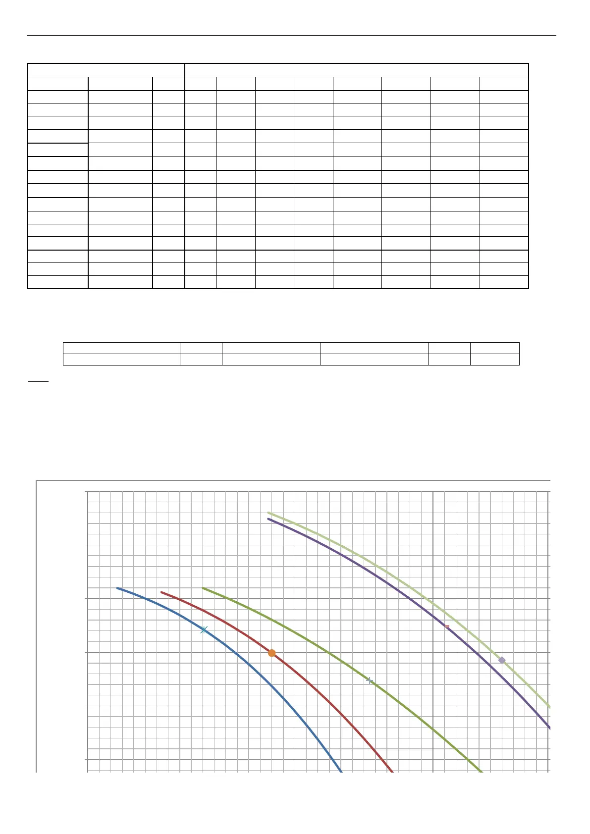
15 AVAILABLE HEAD PRESSURE OF THE UNIT WITH INTEGRATED CIRCULATOR
We reporte below the Head pressure-Water flow characteristic curves without head losses of the hydronic kit (which is composed
of the components describe in the Paragraph 5.10) at the maximum speed of the circulator. The optimal operating point is
indicated on each curve under the specified conditions at the apex (1) p. 23. The plant system must be designed so as to ensure
the nominal water flow rate corresponding to the operating points indicated below.
For nominal points of LT version, please refer to water flow rates that are reported in the table on Paragraph 0.
0
20
40
60
80
100
120
140
0,5 1,0 1,5 2,0 2,5 3,0
Available head pressure [kPa]
Water flow[L/s]
i-HP 0125
i-HP 0135
i-HP 0250/i-HP 0250F
i-HP 0260
i-HP 0270

Table of Contents

Related product manuals