i-HP Industrial inverter air/water heat pumps with axial fans
19
WARNING: The power supply have to respect the listed limits: failing this, warranty will terminate immediately.
Before any operation on the unit, be sure that the power supply is disconnected.
WARNING: The water flow switch (B component in the previous hydraulic circuit and factory installed) has ALWAYS to
be connected following the indications listed in the wiring diagram. Never bridge the water flow switch connections in
the terminal board. Should the water flow switch connections altered or not properly made, the guarantee will be
invalidated.
Install upstream of each unit an adequate protection and disconnection device of the electric power with delayed
characteristic curve, with at least 3 mm contact opening and with an adequate capacity of breaking and differential
protection.
A good grounding is required; the manufacturer is not responsible for damage caused in case of lack of good
grounding.
Use cables that meet the regulations in force in different countries.
If the lightning risk is high, the unit must be protected, the risk assessment must comply with the CEI EN 62305-2
regulation.
If there is a possibility that a lightning can strike the area around the appliance, stop the operation of the unit and
disconnect the system upstream switch.
Make sure to ground the unit.
Do not ground the unit with pipes or lightning rods.
A poor grounding of the unit can result in electrocution.
Warning: Electrostatic discharges can damage the electronic components, before performing any work; ground the
electrostatic charge by touching objects such as water or heating pipes.
Before working on the control panel it is OBLIGATORY to:
Turn off the units from control panel (displayed “OFF”).
Place the general differential QF switch in “OFF” state.
Wait for 90 seconds before getting access to the electrical panel.
Be sure that the grounding connection is good before carrying out any repairs.
Be sure that you are well insulated from the ground, with dry hands and feet, or by using insulating platforms
and gloves.
Check that there is no foreign material near the system.
WARNING: The remote control panel is connected to the water chiller by means of no.4 wires having a 1,5 mm
2
section. The power supply cables have to be separated from the remote control wires. The maximum distance is 50m.
WARNING: The remote control panel cannot be installed in areas with strong vibrations, corrosive gases, and excess
of dirtiness or high humidity levels. Leave free the area near the cooling openings.
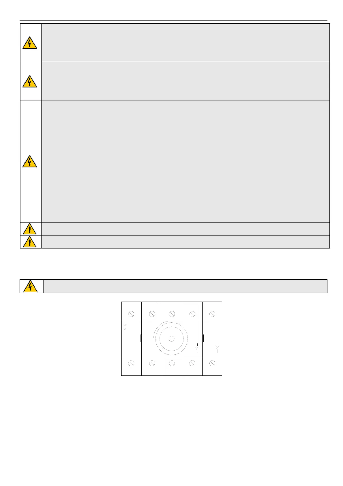
7.6.1 Power supply terminal block
The power supply of the units is 3-Ph/N/PE 400V, 50Hz. The power cables should be brought inside the electrical panel of the unit
and connected to the disconnecting switch inside the electric panel itself, in the bottom at the left, as shown in the following figure:
Electrical wiring has to be done only by qualified personnel.
PE
PE
1
9
3
4
5
2
7
8
PE
PE
2
5
4
3
6
1
8
7
I ON
O
OFF
PE L1 L2
L3
N
The connections of the power supply cables to the disconnecting switch should be done in order from left to right as: protective
earth (PE), phase conductor 1 (L1), phase conductor 2 (L2), phase conductor 3 (L3), neutral conductor (N).
 Loading...