i-HP Industrial inverter air/water heat pumps with axial fans
28
16.3 MODEL i-HP 0260
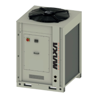
Configuration with integrated circulator, control via 0-10 volt analogic signal
16.4 MOD. i-HP 0260 e i-HP 0270
Curves for the model equipped with pump driven by AC inverter.
16.5 CIRCULATOR CHARACTERISTICS
Pump driven by
AC inverter
Max. absorbed current [A]
EEI (energy efficiency index)
Because of the circulators have got similar prevalence curves to those integrated, please refer to Paragraph 15 for plant designing.
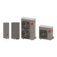
17 HEAD LOSS CURVES OF THE HYDRONIC CIRCUIT
We obtain the pressure head of the circulating pump from the addition of the head losses of the hydronic circuit and the available
head pressure.
For example: for the model i-HP 0125 with nominal water flow 1,01 L/s we obtain: 30 kPa (head loss) + 88 kPa (available head
pressure)=118 kPa (circulator head pressure).
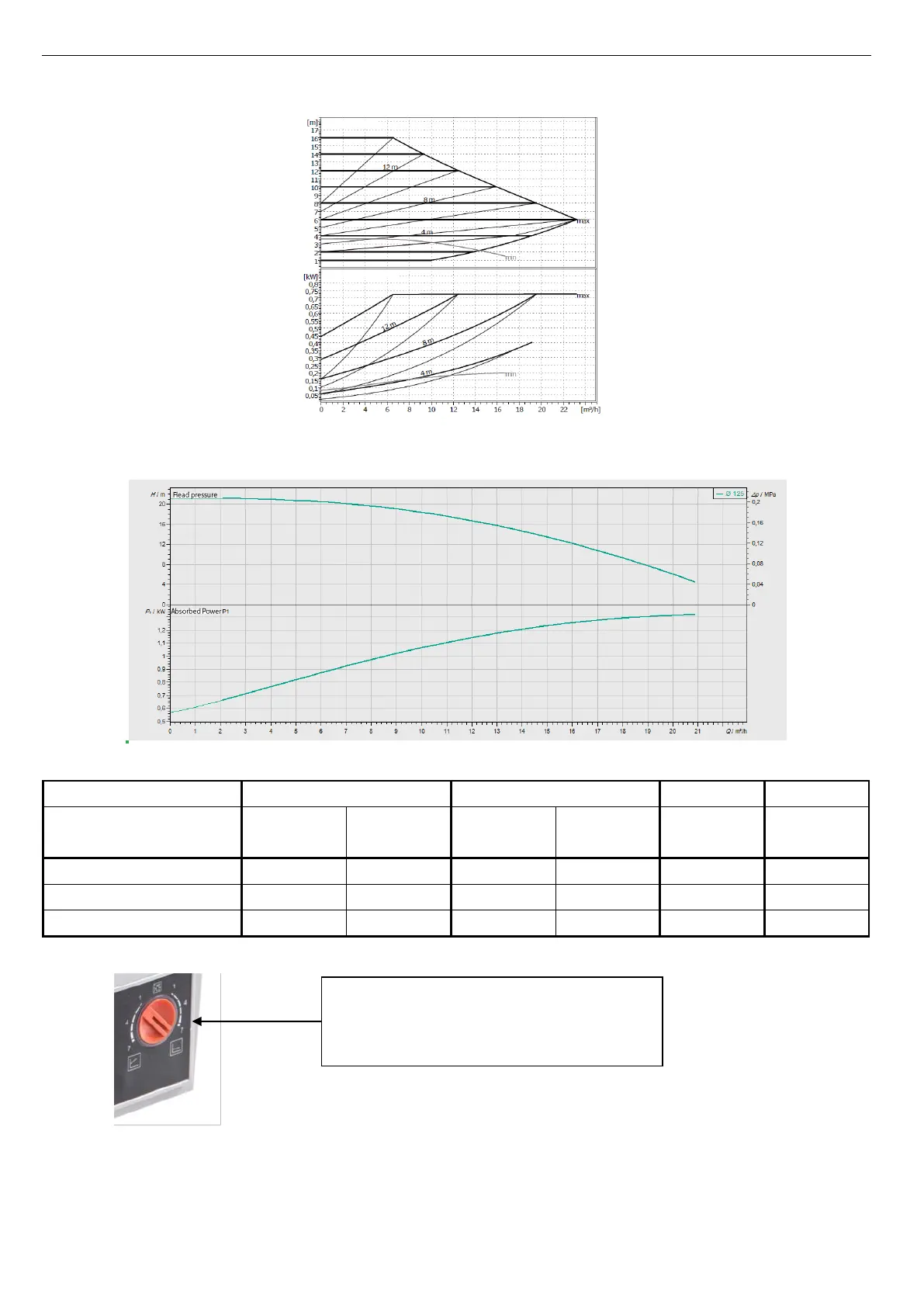
It’s advisable to use:
- the adjustment scale on the right of the knob (constant
P) in the case of use of thermostatic valves on the plant
- the adjustment scale on the left of the knob (variable
P) in the case of use of 3-way valves on the plant
 Loading...