i-HP Industrial inverter air/water heat pumps with axial fans
18
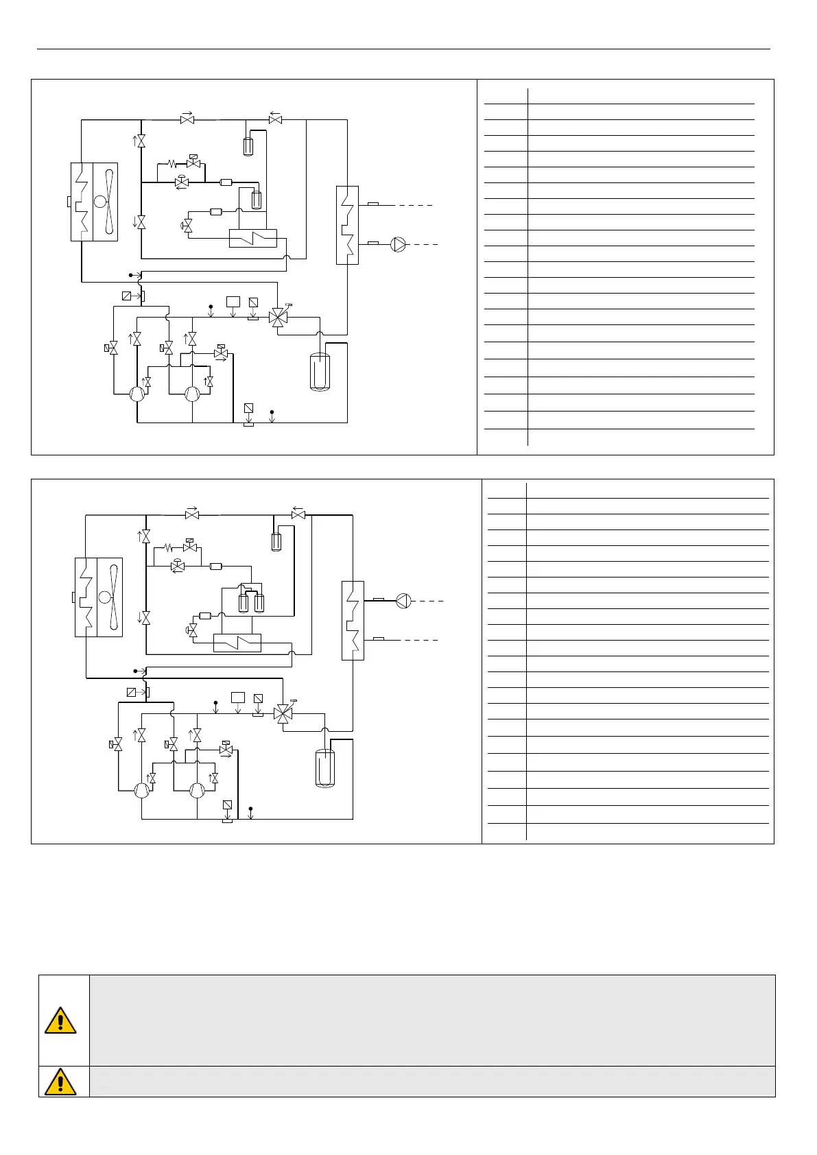
7.5.5 Refrigerant diagram of the model i-HP-LT 0235
LS
i-HP 0235 LT
versione VN
M
SE
NRV
NRV
NRV
NRV
V
V
4WV
P
OUT
IN
ST
LP
DT
HP
Pr
IN
OUT
LR
LS
EEV
INJ
FL
NRV
V
4WV
C
P
M
LP
ST
PV
INJP
INJT
PV
INJT
INJP
PV
Pr
HP
DT
PV
LR
FL
FL
EEV
LR
V
INJ
CP
NRV
NRV
CC
NRV *
V *
NRV *
COMPRESSOR INLET TEMPERATURE
COMPRESSOR OUTLET TEMPERATURE
HIGH PRESSURE FLOW SWITCH
ELECTRONIC EXPANSION VALVE
ON/OFF VALVE WITH SOLENOID
INJECTION PRESSURE TRANSDUCER
7.5.1 Refrigerant diagram i-HP-LT -0250
LS
i-HP 0250 LT
versione VN
M
SE
NRV
NRV
NRV
NRV
4WV
ST
LP
DT
HP
Pr
IN
OUT
LR
LS
EEV
INJ
FL
NRV
V
4WV
C
P
M
LP
ST
PV
INJP
INJT
PV
INJT
INJP
PV
Pr
HP
DT
PV
LR
FL
FL
EEV
LR
V
INJ
CP
LR
OUT
IN
P
V
V
NRV
NRV
CC
NRV *
V *
NRV *
COMPRESSOR INLET TEMPERATURE
COMPRESSOR OUTLET TEMPERATURE
HIGH PRESSURE FLOW SWITCH
ELECTRONIC EXPANSION VALVE
ON/OFF VALVE WITH SOLENOID
INJECTION PRESSURE TRANSDUCER
7.6 ELECTRICAL CONNECTIONS
Check if the power supply circuit meets the unit’s electric nominal data (tension, phases, frequency) reported on the label
attached on the right-side panel of the unit. The wiring must be done in accordance to the wiring diagram attached to the unit and
in conformity with the national and international norms in force (attempting to provide a general magneto-thermic circuit breaker,
differential circuit breakers for each electric line, proper grounding for the plant, etc.). Power cables, electric protections and line
fuses have to be sized according to the specifications listed in the wiring diagram enclosed with the unit and in the electrical data
contained in the table of technical characteristics (see Paragraph 13).
Because of the presence, inside the machine, of EMC filters for compliance with EMC limits (interference emission and
interference immunity), earth fault currents up to 250 mA of intensity can be detected.
For proper installation, electrically connect the unit with a dedicated line; if you use a residual current circuit breaker,
choose a four-pole one, with a trigger threshold of 300 mA and delayed triggering (super-resistant, characteristic K).
The machine must be installed in TN-S/TT power supply grounding systems.
The electrical installation must be carried out in accordance with norms in force.
WARNING: The supply voltage’s fluctuations cannot exceed ±5% of the nominal value. Should this tolerance not be
respected, please contact our technical department.
 Loading...