INSTALLATION3 - 6
DSE-15 www.maxcess.euMI 1094 1
The reflector of the sensor must be inclined at an angle of
+(3°±2°) or -(3°±2°). This will prevent undesirable reflected
light from striking the sensor
If the material is recorded with a glossy or matte surface, the red
light beam should strike the web level at a certain angle.
table and
figure 3.5
A minimum distance must be maintained for reflectors with a
rough structure.
table and
figure 3.5
Alignment of reflector and
sensor To prevent an undesirable change in the web position and guide
point when the web plane changes, the sensor must be mounted
at an angle of 90° to the web surface.
figure 3.6
Note:
If a positioner is used to move the sensor, the red light beam
must strike the reflector along the entire path the sensor moves
without faults.
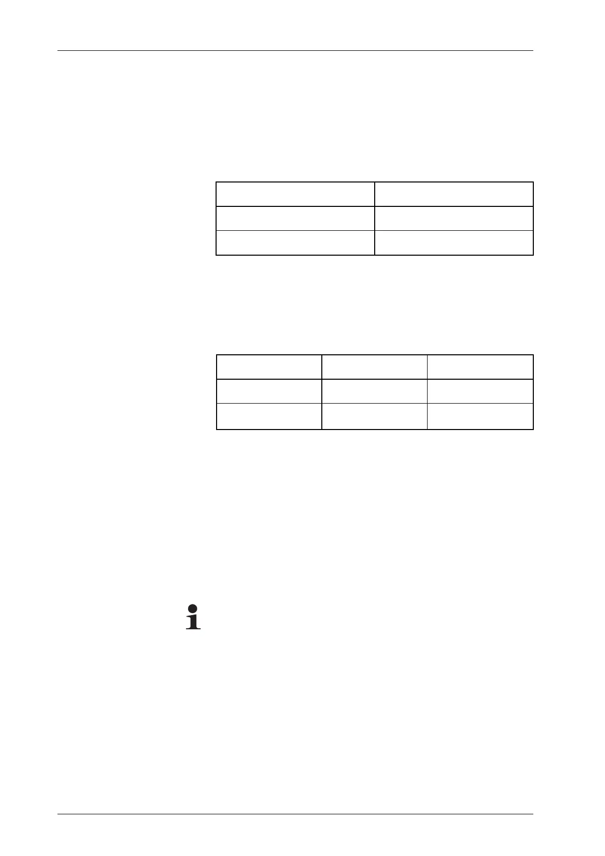
Material W
reflective 5° - 45°
matte 0° - 45°
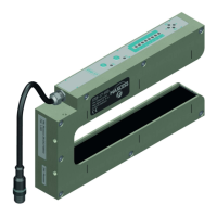
Material X Y
opaque up to 1000mm 10 - 90% of X
transparent 150 - 1000mm
max.
¾X