TROUBLESHOOTING8 - 1
DSE-15 www.maxcess.euMI 1094 1
8 TROUBLESHOOTING
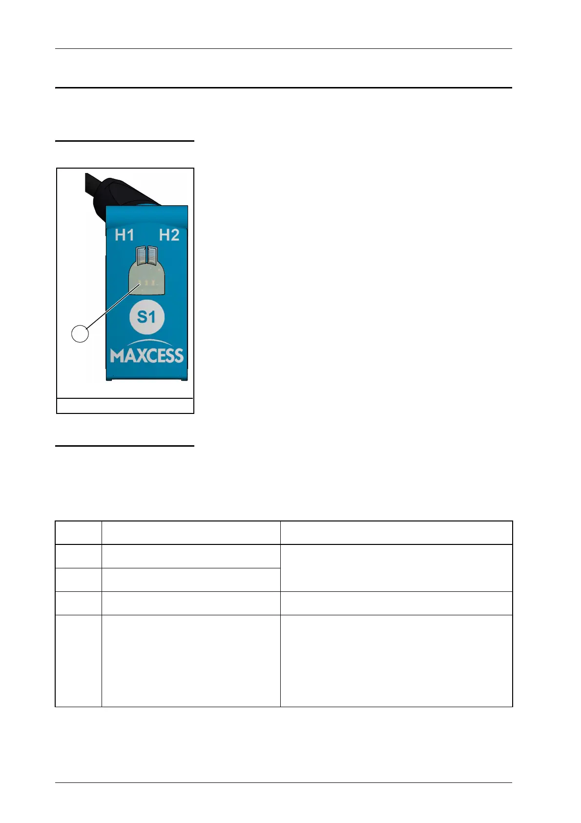
LED display The sensor displays information about the operation state when
the LEDs are lit or flashing. The information is divided into
groups as follows:
Normal operation:
The output signal of the sensor is displayed. The LEDs flicker/
light up depending on the position of the material web within
the sensor field of view.
Error message:
Error n = 1 .. 5:
The output signal of the sensor (10s long) and the flashing pat-
tern of an error are displayed alternately. An error is displayed
until it has been corrected. It is still possible to use the sensor.
Error n = 6 .. 7:
Only the blinking pattern of an error is displayed. The sensor is
no longer supplying a valid output signal.
Fault In the event of an error, the LEDs flash with a certain pattern:
flash n times for 0.5s on - 0.5s off, followed by 1s pause. The
number of flashing pulses between two pauses encodes the
error number "n".
1 - LED display
Figure 8.1: DSE-15 sensor
1
"n" Fault Remedy
1 Undervoltage
Check power supply voltage
2 Overvoltage
3 Overtemperature The error is set at 70°C and canceled at 60°C.
4 Adjustment error – measurement
signal too low
Set up the sensor (again),
Check the mechanical arrangement of the sen-
sor and reflector. Is there not enough reflected
light present?
Setting up the sensor and reflector,
page-5-1