CONTROL ELEMENTS 4 - 1
DSE-15www.maxcess.eu MI 1094 1
Bedienelemente.fm
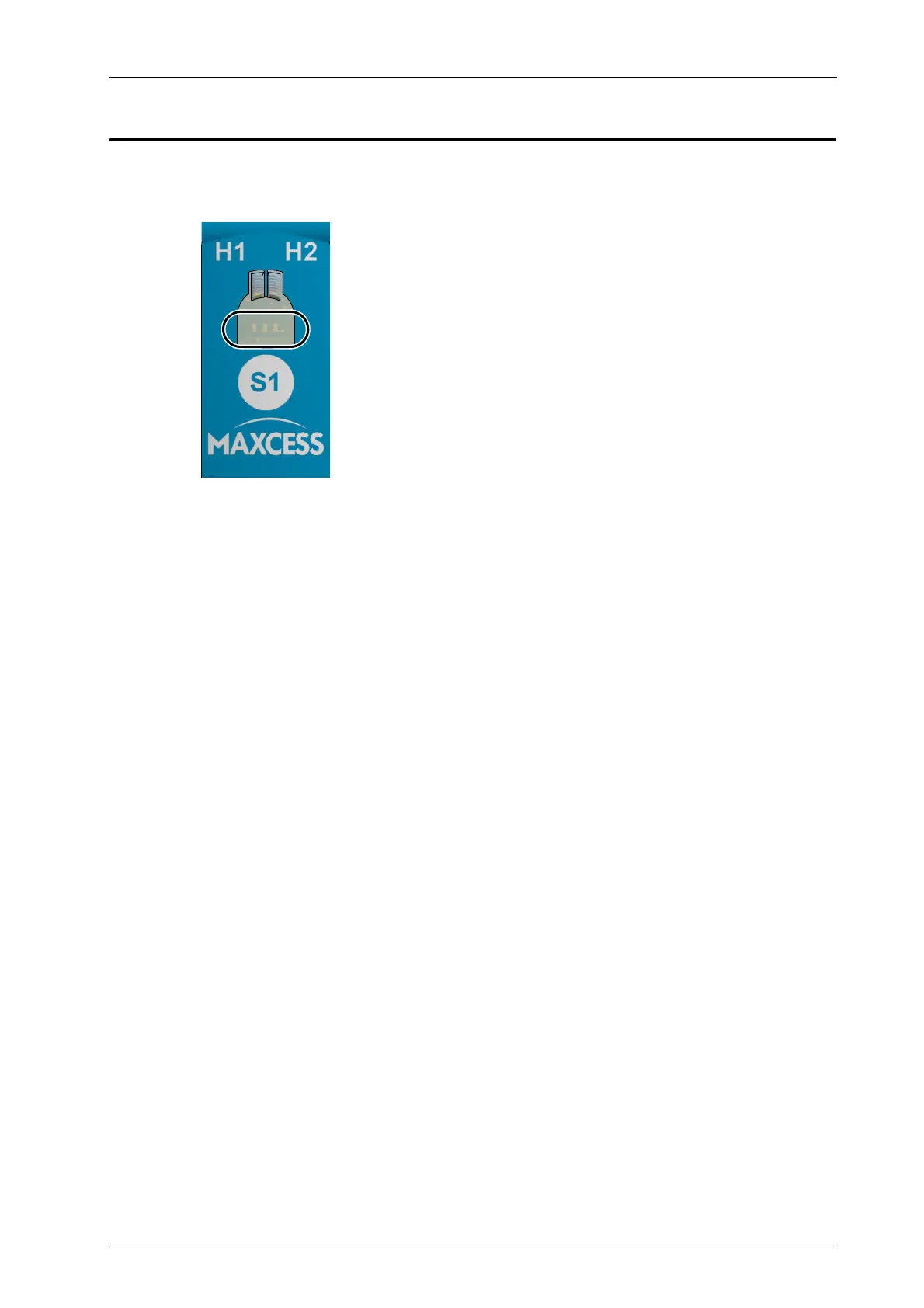
4 CONTROL ELEMENTS
The DSE-15 sensor has the following control and display
elements:
LED H1:
– not assigned
LED H2
– not assigned in its regular operation state
– lit when sensor setup is started
LED display (marked)
– Shows whether the red light beam is covered by the material
web when the sensor is working in the regular operation
state
LEDs in normal operation, page 6-1
– Indicates that the sensor has been set up to the reflector
when the two outer LEDs alternate flashing with the inner LED
Setting up the sensor and reflector, page 5-1
– Indicates an error when all the LEDs flash simultaneously
Troubleshooting, page 8-1
S1 key
– Start the sensor setup
The S1 key is a capacitive touchpad. Make certain there are
no metallic objects on or in the immediate vicinity of the key.
figure 3.2