TECHNICAL DATA 9 - 2
DSE-15www.maxcess.eu MI 1094 1
TechnDaten.fm
Electrical connection Power supply
10V ... 28V
(PELV, negative potential connected to ground
Overcurrent protection device slow-blow max. 2A)
Power consumption
<600mW
Output signal
0 - 10mA to ≤ 400Ω at 12V (10…15V) Power supply
4 - 20mA to ≤ 200Ω at 24V (20…28V) Power supply
Digital data exchange via RS-485 when connected to selected
FIFE web guide controllers (e.g. D-MAXE)
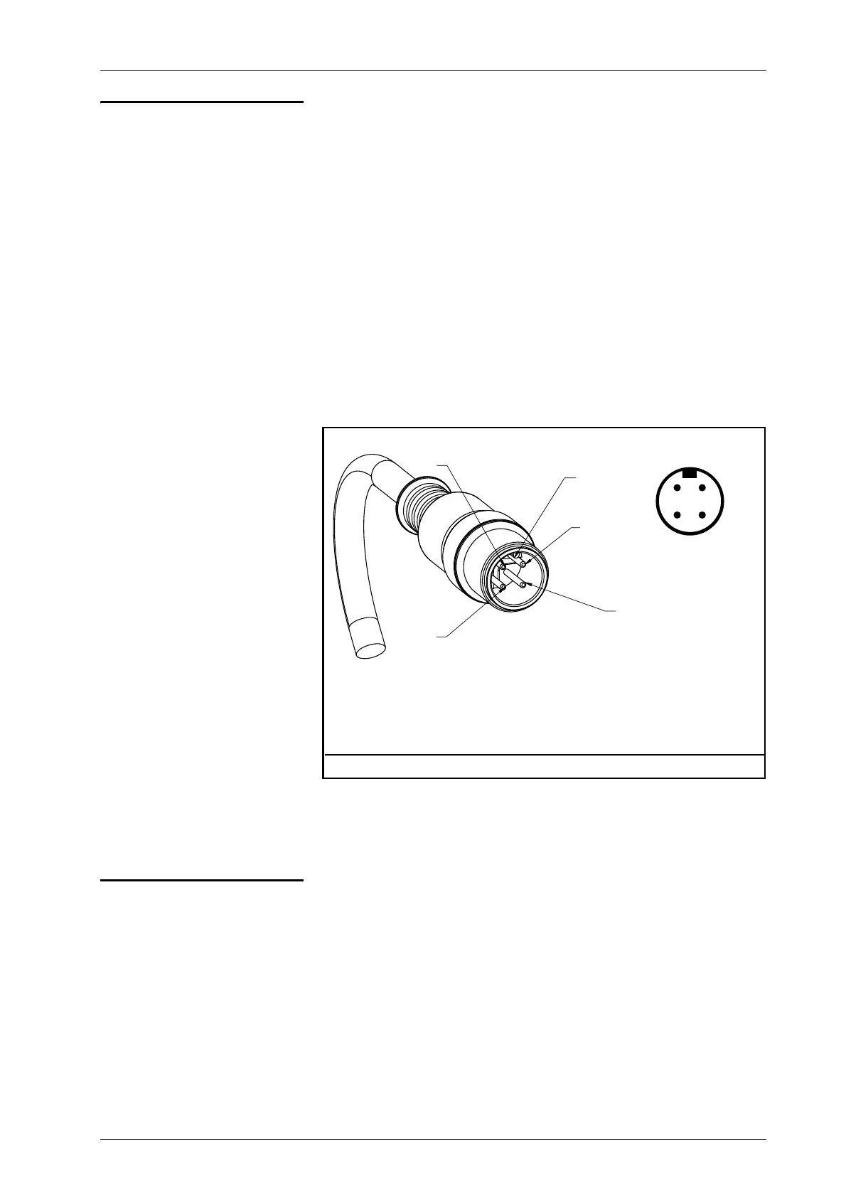
Pin assignment
Standards The DSE-15 sensor was constructed in accordance with the
standards and regulations of the European Union. A Declaration
of Conformity is available.
1 Power supply
2 Output signal (RS-485)
3P-GND
4 Output signal (analogue
or RS-485)
XKey
Housing = Shield
Figure 9.1: M12 connector