5-10t Internal Combustion Counterbalance Forklift Truck Operation & Maintenance Manual
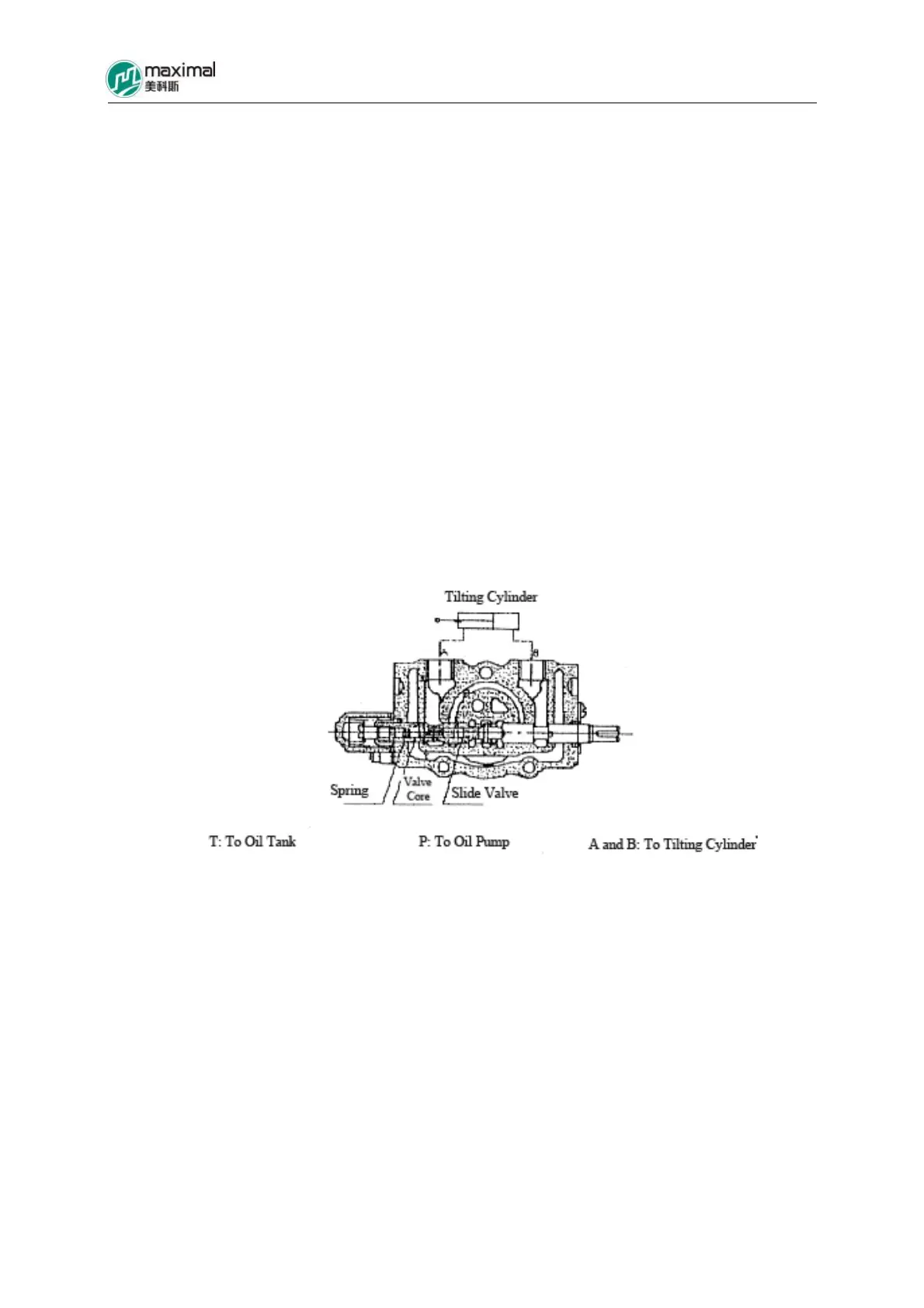
7.6 Work of Tilt Auto-locking Valve
The tilt auto-locking valve is used to prevent the shake of mast (arisen from the possibly generated
internal negative pressure inside the tilt cylinder), and at the same time also to avoid the danger for
mast to be tilted arising from misoperation (bump into the tipping control lever), when engine is
flamed out. In conventional structure, even if the engine wants to stop rotation, the mast will also tip
forward due to bump into tilt operating lever. However, after this new-type of tilt self-locking part is
used, under the abovementioned circumstances, the mast will not tip forward, and it will not tip
forward, even if the tilt operating lever is forcibly pushed. Refer to Fig 7-9 for the structure of the tilt
auto-locking valve. In the drawing, the joint A is connected to the front side of the tilt cylinder, while
the joint B is connected to the rear side of the tilt cylinder. When tilt operating lever is pulled, (the
slide valve pulled out), the oil from the oil pump flows into the joint A, while the oil from the joint B
returns to the oil tank, and accordingly the mast will tip backward. When tilt operating lever is
pushed (slide valve pushed in), the oil from the oil pump flows into the joint B, and the auto-locking
valve in the tilt slide valve is enabled, by virtue of HP oil, for the joint A to be connected to LP, while
the mast will tip forward accordingly. However, in the case when engine is turned off, as there is no
HP oil to enable the auto-locking valve, the joint A will not be connected to LP, and the mast will not
tip forward, while negative pressure will not be generated inside the tilt cylinder.
Fig 7-9 Tilt Self-locking Valve
7.7 Control Device of Multi-way Valve (Refer to Fig 7-10.)
Respective slide valves of multi-way valve are controlled by different control handles that are
mounted on one same shaft. The shaft is mounted on the bracket on the front instrument bracket, and
different control levers on it are passed onto the respective slide valves of the multi-way valve
through connecting rod.
7.8 Oil Tank
The hydraulic oil tank is installed on the right side of the truck frame, and the suction oil filters for
the front and rear oil pumps, the oil filler cap with oil leveler, and the brake return oil pipe used
during power brake are mounted on the oil tank cover. Refer to Fig 7-11.