5-10t Internal Combustion Counterbalance Forklift Truck Operation & Maintenance Manual
1.5.6 Adjustment of Valve Clearance
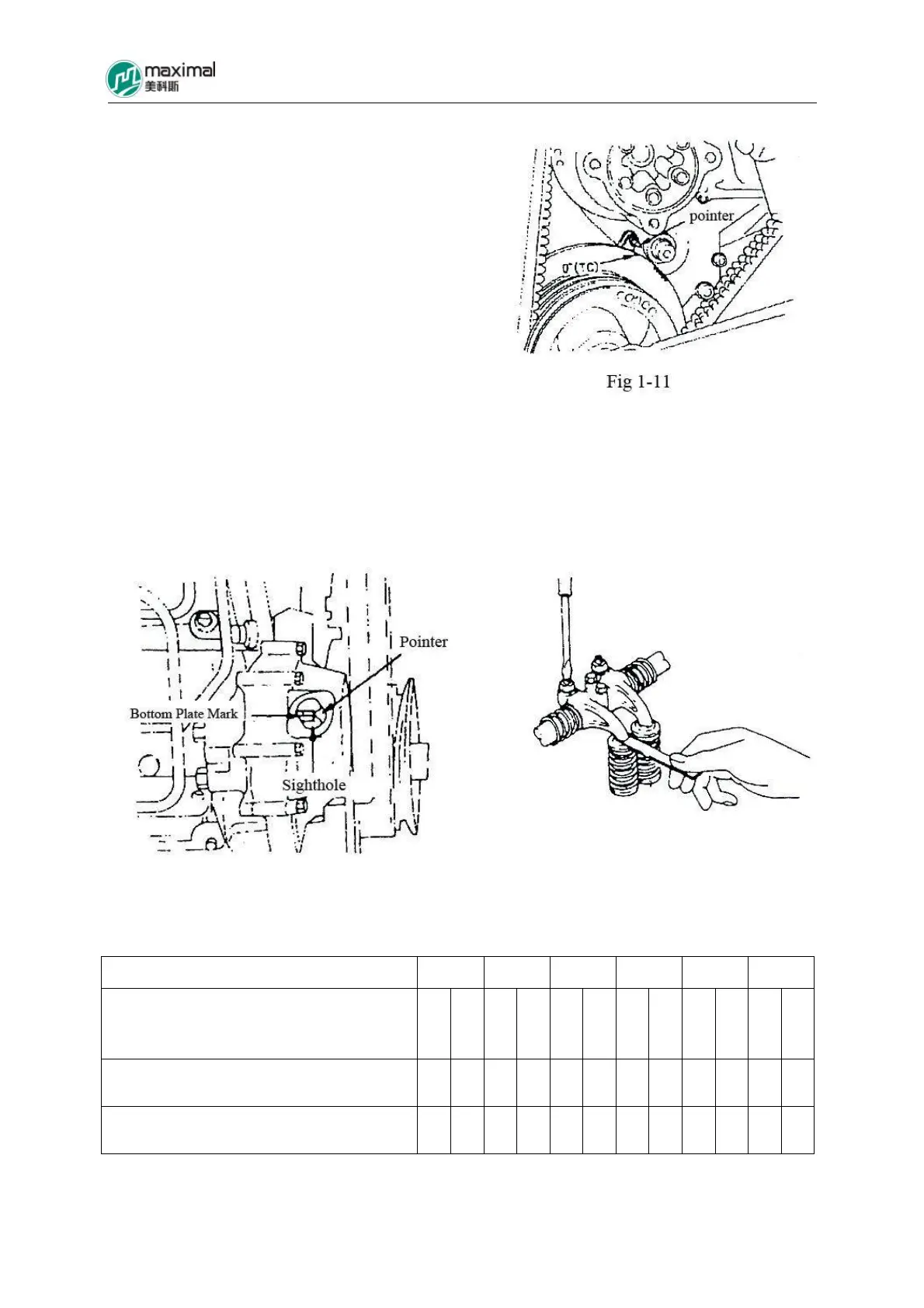
(1)Turn the crankshaft in the clockwise direction,
for the “TC” mark of belt pulley shock absorber
and the pointer to be superposed with each other.
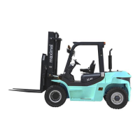
(2)Open the inspection cover, and confirm the
positions of bottom plate mark and the pointer.
If the positions of bottom plate mark and the
pointer are consistent, it indicates upper dead
center of compression stroke for the 1
st
cylinder.
Adjust the valve clearance of “ ”△ countermark,
and adjust the valve clearance of “ ”※ countermark as well.
Valve Clearance Value: 0.4mm (the same value for both suction and exhaust, under the cold
status)
Refer to Figs 1-11, 1-12, and 1-13 for details.
Fig 1-12 Fig 1-13
Refer to Table 1-2 for specific adjustment.
Cylinder Sequence Number
1 2 3 4 5 6
Valve Sequence Number
I: Suction Valve
E: Exhaust Valve
I
E
I
E
I
E
I
E
I
E
I
E
Upper Center for 1
st
Cylinder Compression
Stroke
△
△
△
△
△
△
△
Upper Center for 6
th
Cylinder Compression
Stroke
※
※
※
※
※