5-10t Internal Combustion Counterbalance Forklift Truck Operation & Maintenance Manual
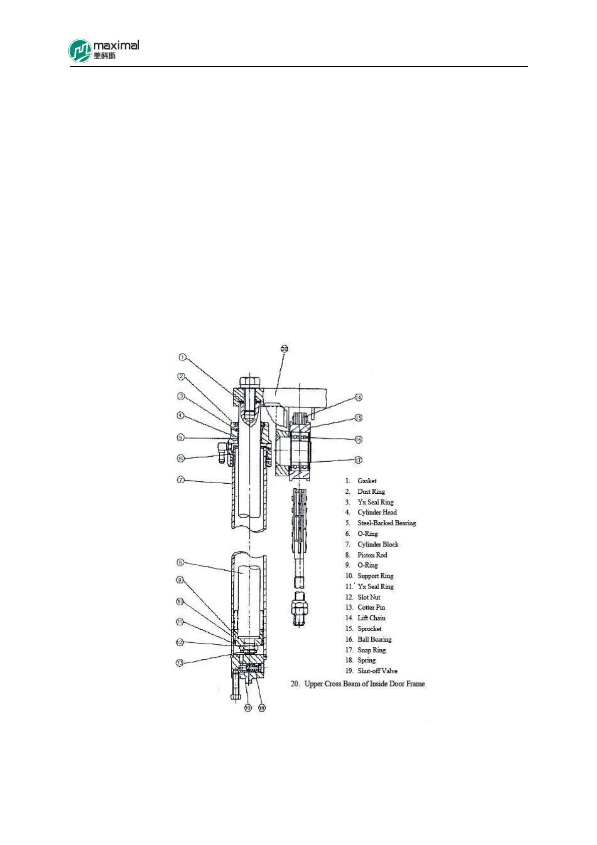
The piston and the piston rod are fixed together using slot nut, cotter pin, and o-ring, while Yx seal
ring, retainer ring, and support ring are mounted on the external circumference of the piston. For the
action of HP oil, the piston moves upward along the internal surface of the cylinder block. Dust ring
and steel-backed bearing are installed on the cylinder head that is screwed into the cylinder block
depending on thread. The steel-backed bearing is used to support piston rod, while dust ring is to
prevent the entry of dust into the cylinder. On the top of the cylinder, the tail part of the piston rod
and the upper cross beam of the inner mast are fixed using bolts.
When lift control lever is pulled backwards, the HP oil is introduced into the cylinder through the oil
inlet port of the lift cylinder and drives the piston rod and the walking beam, for the Fork to rise
through chain. When the inner mast just begins to rise, the height from the ground to the position of
Fork is called the free lifting height, and the height of mast does not change, within this range.
While the lift control lever moves forward, due to the deadweights of piston rod, Fork Carriage,
cargo stop frame, and Fork, the piston is dropped, and drain the oil under the position out of the
cylinder block. The speed of the oil drained from the cylinder block is controlled by the limiting
valve (throttle valve), and the oil returns to oil tank through multi-way valve.
Refer to Fig 8-1 for the structure of lift cylinder for 5-8t forklift trucks. Refer to Fig 8-2 for the
structure of lift cylinder for 10t forklift truck.
Fig 8-1 Lift Cylinder (5-8t Forklift Trucks)