5-10t Internal Combustion Counterbalance Forklift Truck Operation & Maintenance Manual
8.4 Tilting Cylinder
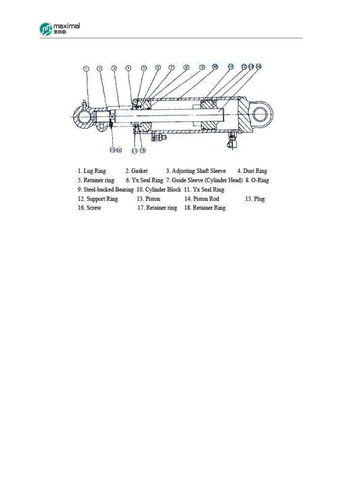
Fig 8-6 Tilt Cylinder
Two double-action tilt cylinders are installed on the two sides of mast. The end of piston rod in the
front part of tilt cylinder is connected with mast, and the cylinder bottom at the rear end of tilt
cylinder is connected with frame using pins. The tilt cylinder assembly is mainly composed of
cylinder block, guide sleeve, piston, and piston rod.
Piston is welded onto the piston rod, and 2 Yx seal rings and one support ring are fitted on the
surface of external circumference of the piston. The piston moves inside the cylinder block, under the
effect of hydraulic oil pressure.
A steel-backed bearing is pressed and fitted in the inner hole of the guide sleeve (cylinder head), and
a Yx seal ring and a dust ring are additionally mounted, used to prevent oil leak (between piston rod
and guide sleeve and the dust. One o-ring is installed on the surface of the external circumference of
the guide sleeve that is screwed into the cylinder block.
When tilt operating lever is pulled forward, the HP oil enters into the cylinder from the bottom of the
cylinder, for the piston to move forward, and accordingly the mast will tip forward (reachable to 6°),
and when tilt operating lever is pulled backward, the HP oil enters into the cylinder from the front
guide sleeve, for the piston to move backward, and accordingly the mast will tip backward (reachable
to 12°).