5-10t Internal Combustion Counterbalance Forklift Truck Operation & Maintenance Manual
3.4 Hydraulic Clutch
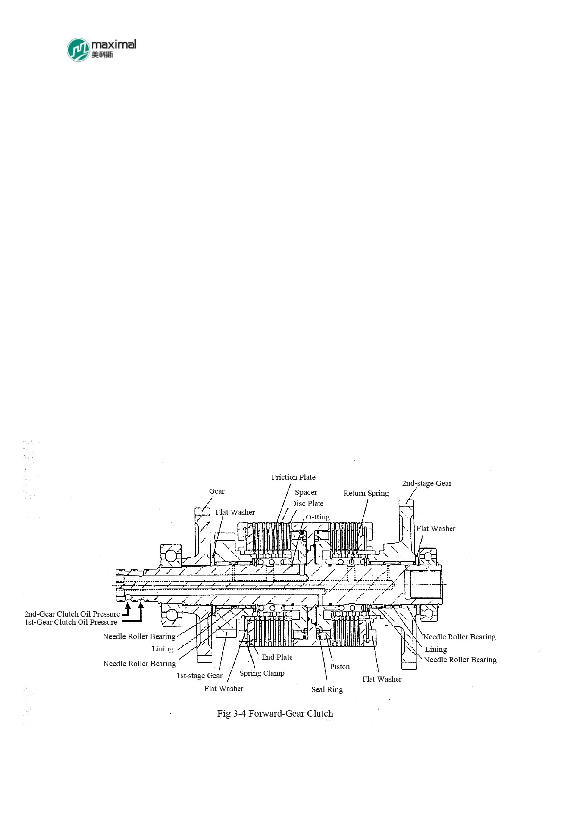
Refer to Fig 3-4 for forward gear clutch, and refer to Fig 3-5 for backward gear clutch.
Hydraulic clutch is installed inside the transmission, and the driving gear on the side of wet
multi-disc is engaged with its corresponding driven gear, while the driving gear on the side of
backward-gear clutch is engaged with its opposite shaft gear.
Six friction plates manufactured with sintered material and 7 steel spacers are contained,
inside one clutch unit, and they are alternately assembled and mounted together with pistons.
During operation, the sealing property for external circle and internal circle of piston is
respectively ensured by slide oil seal and O-ring. Under the status out of service, the disc
return spring is disengaged from hydraulic clutch, and the surface of clutch is always
lubricated by the oil returned from oil cooler, to prevent surface adhesion and wear of clutch.
When the pressure oil acts on the piston, the sintered friction plates and steel spacers
alternately assembled together are pressed, and therefore the clutch as a whole transmits the
power from the torque converter to the driving gear.
Accordingly, the power transmission flow between torque converter – transmission is as
follows:
Turbine – Input Shaft – Clutch Drum – Steel Spacer – Sintered Friction Plate – Forward or
Backward Gear – Output Shaft