5-10t Internal Combustion Counterbalance Forklift Truck Operation & Maintenance Manual
(4)Fix the o-ring and the rubber cut onto the head of the slide valve, and screw down the sealing plate
using bolts, at a tightening torque of 4.6~5.8N·m.
(5)Fit in the one-way valve, spring, and o-ring into each one-plate valve, after being assembled, and
then use three connecting bolts to tighten it up according to the specified torques (103N.m for one
bolt, and 66N.m for the other).
7.10.3 Notices
The pressure for respective safety valves in multi-way valve has already been properly adjusted
before factory delivery of the forklift truck, and user shall not make adjustment at discretion during
use, to avoid damage of hydraulic system and hydraulic components due to too high pressure
adjustment. Adjust the pressure for respective safety valves correctly according to the requirements
of the manual after maintenance.
8. Lift Cylinder and Tilt Cylinder
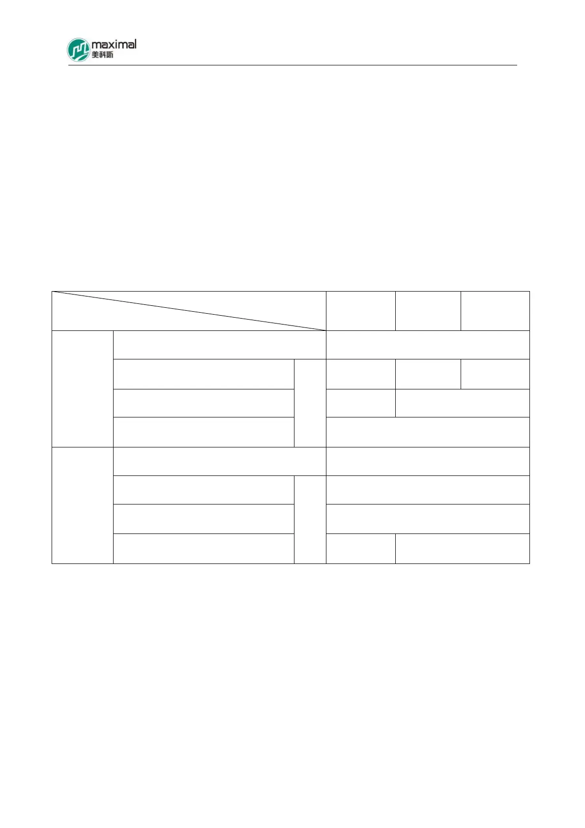
Refer to Table 8-1 for main technical parameters.
Table 8-1
Forklift Truck Tonnage
Item
5-7t 8t 10t
Type Single-Action Piston Type
Inner Diameter of Cylinder Φ80 Φ90 Φ100
Outer Diameter of Piston Rod Φ60 Φ70
Lift Cylinder
Cylinder Stroke
㎜
1495
Type Double-Action Piston Type
Inner Diameter of Cylinder Φ115
Outer Diameter of Piston Rod Φ50
Tilt Cylinder
Cylinder Stroke(6°/12°)
㎜
227 242
8.1 Lift Cylinder
Two single-action lift cylinders are respectively fixed in the rear area of the both sides of the outer
mast. The bottom of cylinder is fixed on the bracket for the cylinder on the outer mast, while the top
part of the cylinder, or the tail part of the piston rod is connected with walking beam using bolts. The
strokes for the two lift cylinders shall be consistently adjusted, for the two cylinders to be
synchronous. They shall be adjusted through bolt if not synchronous (Refer to Fig 8-1).
The lift cylinder is mainly comprised of cylinder block, piston, piston rod, and cylinder head. There
is one oil inlet port in the lower part of the cylinder block, and the HP oil enters therefrom. In the
upper part of the cylinder block, there is an oil outlet port under the Yx seal ring of the piston, and
the LP oil is drained therefrom (The oil outlet port is connected with oil return pipe.).