5-10t Internal Combustion Counterbalance Forklift Truck Operation & Maintenance Manual
8.2 Isolating Valve
Isolating valve is installed on the bottom of the two lift cylinders (Refer to Fig 8-1 Sequence 19 or
Fig 8-2 Sequence 18). When HP hose is suddenly cracked, the valve is able to prevent sharp drop of
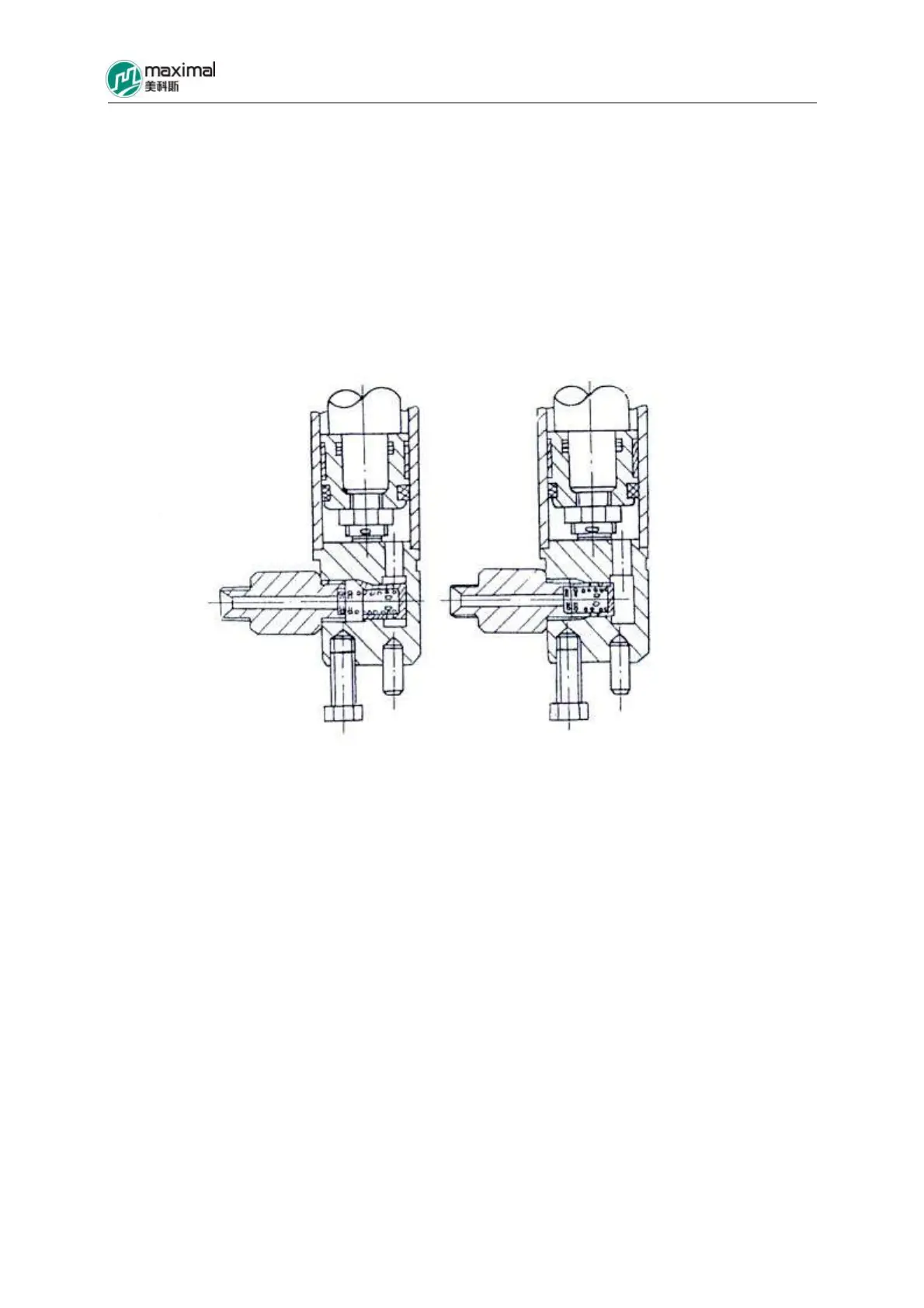
cargo. Refer to Fig 8-3 for the structure of isolating valve. The return oil from the lift cylinder passes
through the isolating valve, and the oil holes around the slide valve allow the two cavities to give rise
to pressure difference. When this pressure difference is smaller than the spring force, the slide valve
is not actuated. If the HP hose is suddenly cracked, and only a small quantity of oil flows though the
pores on the end face of slide valve, the fork will drop at a slow speed accordingly.
When Normal When Disconnected
Fig 8-3 Isolating Valve
8.3 Limiting Valve
The limiting valve (namely throttle valve) is mounted on the oil circuit between the multi-way valve
and the HP oil port of the two lift cylinders, positioned close to the left lift cylinder (Refer to Fig 8-4.)
Limiting valve is used to limit the dropping speed of fork when it is heavily loaded, and refer to Fig
8-5 for its structure. With regard to 8t and 10 t forklift trucks, their structures are basically similar to
those of the 5-7t forklift trucks, as indicated in Fig 8-5 Sequence 3, while speaking from the 8t
forklift truck, it has a tapered spiral spring, while 10t forklift truck is availed with a disc spring.
The limiting valve also plays the function as a safety device, in addition to control over the cargo
dropping speed, namely for certain factor, the rubber hose between the multi-way valve and the lift
cylinder is damaged, at this point, the limiting valve plays the part as a safety device (preventing
danger arising from sharp drop of cargo).
The work of limiting valve is described as follows:
Refer to Fig 8-5. When fork rises, the HP oil from the multi-way valve flows into the cavity “A”, and
drives the valve sleeve to move leftwards, thus to turn on the opening “G”, for the HP oil to flow