5-10t Internal Combustion Counterbalance Forklift Truck Operation & Maintenance Manual
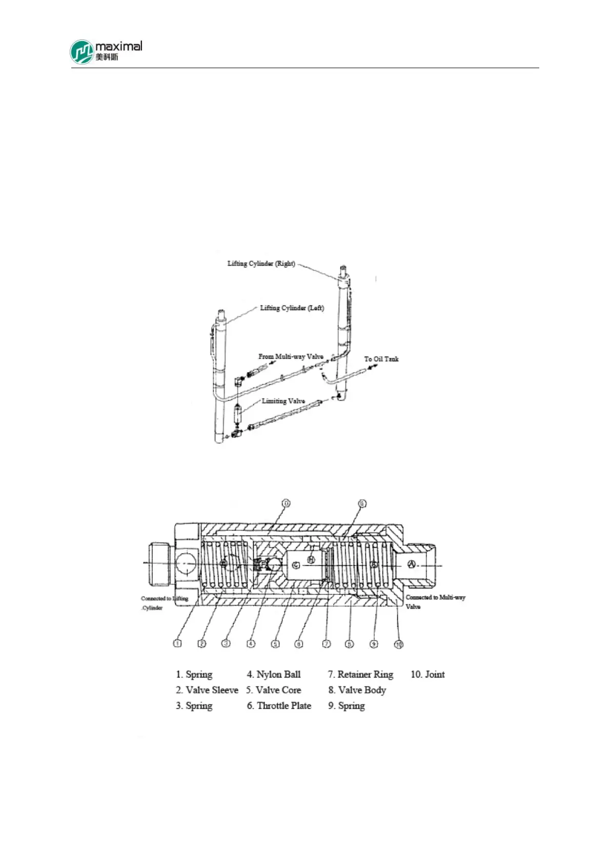
along two routes (A-B-G-D-E and A-B-C-D-E), with both of these two circuits of HP oil flowing into
the lift cylinder. In this case, the flow rate of oil is not adjusted and limited. When fork begins to drop,
the return oil drained from inside the lift cylinder enters into the cavity “E” and drives the valve
sleeve to move rightwards, until the valve sleeve gets into contact with the joint, namely the opening
“G” is closed. Accordingly the return oil must pass the throttle plate to flow back to oil tank through
E, D, H, C, B, and A. if the amount of return oil drained from inside the lift cylinder is abruptly
increased, the pressure in cavity “F” goes up, and drives the valve core (Fig 8-5 Sequence 5) to
overcome the spring force and move rightwards, for the opening “H” to be narrowed. Consequently,
the oil flow into the cavity “C” from the cavity “D” is reduced, namely the dropping speed of fork is
limited (slowed down).
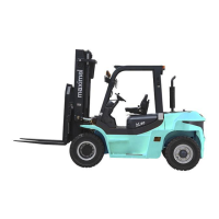
Fig 8-4 Assembling Position for Limiting Valve
Fig 8-5 Limiting Valve (5-7t Forklift Trucks)