FOR SERVICE TECHNICIAN’S USE ONLY
32
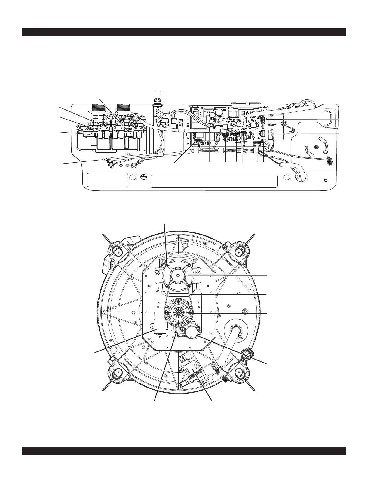
Figure 8 - Bottom View - PSC
COMPONENT LOCATIONS
Figure 7 - Main Control (ACU)
PSC Motor Connector
PSC Motor Connector
Drive Belt
Shaft Pulley
Shifter Assembly Connector
Shifter Assembly
Run Capacitor
6. If the preceding steps did not correct the lock problem, replace the main control.
a. Unplug washer or disconnect power.
b. Replace the main control.
c. Reassemble all parts and panels.
d. Plug in washer or reconnect power. Perform Service Diagnostics to verify repair.
Bleach / Oxi Valve
Faucet Switch
Connector
J3
Hot water Valve
Cold water Valve
Fabric Softener Valve
J1
J14
J13 J5
J9
J4
J11
J10