Do you have a question about the Maytag Pet Pro and is the answer not in the manual?
Provides introductory information for the technical manual.
Outlines the purpose and objectives of the technical manual for service professionals.
Provides essential safety information for operating and servicing the appliance.
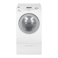
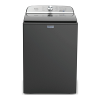
Details the technical specifications of the Maytag Pet Pro System Top Load Washer.
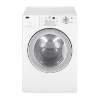
Highlights the key features and capabilities of the washing machine.
Explains the meaning of characters in the model number for identification.
Indicates where to find model, serial number, and tech sheet labels.
Lists physical dimensions and external characteristics of the appliance.
Provides specific functional details and control panel layout.
Details available wash cycles, options, and modifiers for customization.
Lists additional features, certifications, and essential electrical specifications.
Explains the function of each button and knob on the control panel.
Describes how to operate power, select cycles, and manage start/pause functions.
Explains how to adjust temperature, add rinses, and use Deep Water.
Explains how to use the Pet Pro and Fabric Softener modifier options.
Explains the meaning of prefixes and codes in the model number.
Shows the location of the model and serial number label on the appliance.
Specifies the location where the technical service sheet can be found.
Provides an overview of the service guide for the Maytag washer.
Provides instructions on how to enter the service diagnostic mode on the washer.
Explains how to interpret binary codes displayed via LEDs for diagnostics.
Details the User Interface (UI) test procedure for diagnosing control issues.
Outlines the steps to run the automatic test mode for comprehensive diagnostics.
Provides a chart mapping test steps to component activation and HMI response.
Describes how to access and view the washer's software version information.
Presents a chart detailing the diagnostic cycle steps, functions, and timing.
Lists and explains fault codes and their recommended troubleshooting procedures.
Checks to perform before servicing the washer, including power and water supply.
Step-by-step instructions for entering the service diagnostic mode.
Guidance for troubleshooting unsuccessful entry into service mode.
How fault codes are displayed upon service mode activation.
Explains the function and interpretation of the main control board's diagnostic LED.
Details button presses and their corresponding functions within service mode.
Describes the expected behavior of the washer after specific button presses.
Explains how to interpret binary codes using LEDs and a value table.
Details the entry procedure and diagnostic tests for the User Interface.
Instructions on how to properly exit the UI test mode.
How active fault codes are shown during the automatic test.
Steps to initiate the automatic test mode for comprehensive diagnostics.
Instructions on how to properly exit the automatic test mode.
Tests for water valves and drain pump operation.
Tests for lid locking and shifter engagement for wash/spin.
Tests for motor spin speed and lid unlocking function.
Steps to enter and view the washer's software version information.
Procedure for navigating through saved fault codes.
Instructions on how to clear stored fault codes from the system.
Details how to enter factory modes and perform calibration cycles.
Tests for warm, hot, and cold water filling via the detergent valve.
Tests for drain pump operation and lid locking mechanism.
Tests for shifter, motor, and lid unlocking functions.
Fault for excessive suds preventing spin or pressure sensor issues.
Fault for load size exceeding capacity or mechanical friction.
Fault when water temperature is too high for final spin speed.
Fault indicating an off-balance condition detected during the cycle.
Fault when clothes are detected during the clean washer cycle.
Fault indicating too much residual water is detected.
Fault for off-balance condition after user interventions.
Indicates a fault with the main control board (ACU).
Fault indicating a button on the user interface is continuously activated.
Fault indicating the HMI is disconnected from the ACU.
Fault for an out-of-range or absent pressure signal.
Fault indicating the lid switch is not properly detected when lid is open or closed.
Fault when the lid lock mechanism prevents unlocking.
Fault when the lid lock mechanism fails to engage.
Fault for lid not opening or closing properly between cycles.
Fault indicating no communication detected between HMI and ACU.
Fault when ACU cannot read speed or power from the tachometer.
Fault when shifter is not engaging the basket for spin or disengaging for wash.
Fault when the shifter fails to engage the basket correctly.
Fault indicating an open motor circuit line.
Fault when the motor cannot reach the target RPM.
Fault when water level does not change or is not detected correctly.
Fault for water level exceeding capacity or improper hose installation.
Fault for water detected in tub with lid open for too long.
Fault when water level does not change after the drain pump is on.
Provides a guide for troubleshooting common issues with the Maytag washer.
Details the connectors and pin assignments for the main control board.
Outlines specific tests to diagnose component malfunctions.
Indicates the physical locations of various components within the washer.
Steps for when the washer has no power or display response.
Steps for when the washer does not start after pressing START.
Steps for when the user interface does not accept input.
Steps for when the washer does not fill with water.
Steps for when the washer overfills with water.
Steps for issues with fabric softener or Oxi dispenser not working.
Steps for incorrect water temperatures during cycles.
Steps for when the washer does not agitate.
Steps for when the washer does not spin.
Steps for when the washer does not drain.
Steps for cycles taking longer than usual.
Steps for common issues leading to poor wash results.
Guide for identifying and resolving issues with pinched wires in the harness.
Pinouts for water valves, bulk pump, and bulk sensor connectors.
Pinouts for power, PSC motor, and washer interface connectors.
Pinouts for faucet switch, lid lock, and tachometer connectors.
Tests incoming and outgoing power for the main control board.
Checks electrical connections and resistance of water inlet valves.
General test for motor and shifter related faults.
Tests shifter connections, coil, and harness for proper function.
Pinout chart for shifter to main control and drain pump connections.
Resistance values for motor windings.
Table mapping ACU connector pins to HMI pins.
Table of approximate resistance values for the thermistor at different temperatures.
Checks water level sensing components and resistance values.
Checks harness continuity and resistance for the drain pump.
Checks resistance values for lid lock motor winding and switches.
Shows the locations of the cold, hot, and bleach/oxi water inlet valves.
Shows the locations of faucet switch, main control, and shifter connectors.
Shows the locations of the PSC motor, drive belt, shaft pulley, and shifter.
Shows the location of the drain pump.
Procedures for removing the washer console and user interface.
Procedures for removing the water inlet valve and main control board.
Procedures for removing the pet hair filter and agitator.
Procedures for removing the tub ring, basket, and lid lock.
Procedures for removing the lid, hinge, and shifter assembly.
Procedures for removing the drain pump, belt, motor, splutch, and gearcase.
Step-by-step instructions for safely removing the washer console.
Step-by-step instructions for safely removing the user interface.
Step-by-step instructions for removing the water inlet valve.
Step-by-step instructions for removing the main control board.
Step-by-step instructions for removing the pet hair filter.
Step-by-step instructions for removing the agitator.
Instructions for lifting and removing the top panel of the washer.
Step-by-step instructions for removing the tub ring.
Step-by-step instructions for removing the wash basket.
Step-by-step instructions for removing the lid lock mechanism.
Step-by-step instructions for removing the glass lid.
Step-by-step instructions for removing the washer hinge.
Step-by-step instructions for removing the shifter assembly.
Step-by-step instructions for removing the drain pump.
Step-by-step instructions for removing the drive belt and motor.
Step-by-step instructions for removing the splutch assembly.
Step-by-step instructions for removing the gearcase.
Additional steps for removing the gearcase.
Contact information for product specifications and warranty in the US.
Contact information for product specifications and warranty in Canada.
| Capacity | 5.2 cu. ft. |
|---|---|
| Pet Pro Filter | Yes |
| Wash Cycles | 12 |
| Energy Star Certified | Yes |
| Type | Front Load |
| Steam Function | Yes |
| Smart | Yes |
| Color | White |
| Pet Pro Cycle | Yes |
| Load Type | Front Load |
| Voltage | 120 V |