PAGE 16
FOR SERVICE TECHNICIAN’S USE ONLY
DO NOT REMOVE OR DESTROY
1. Unplug dryer or disconnect power.
2. Remove top panel to access the machine
electronics.
3. Remove connector P14 from the CCU
and measure the resistance between P14-3
and P14-6 at the connector. The following
table gives temperatures and their associated
resistance values.
NOTE: All thermistor resistance measurements
must be made while dryer is unplugged and
connector removed from CCU.
If the resistance is OK, the outlet thermistor
is good. Proceed to step 4.
If the thermistor resistance does not agree
with the table, replace the outlet thermistor.
4. Check P14-3 and P14-6 to dryer cabinet
ground. If either pin indicates continuity
to ground (short), replace wiring harness;
otherwise, proceed to step 5.
5. If the preceding steps did not correct the
problem, replace the CCU.
Temperature Levels Incorrect – If no error code
is displayed and the connections to the thermistor
are good, check the exhaust temperature value
at any or all of the temperature levels in question,
using the “timed dry” cycle.
1. Remove load from dryer and disconnect
external vent.
2. Plug in dryer or reconnect power.
3. Run a “timed dry” cycle of at least 5
minutes in duration. Select high, medium
high, medium, low, or extra low.
4. Using a calibrated temperature probe,
take a temperature measurement in the
center of the exhaust outlet. The correct
exhaust temperatures are as follows:
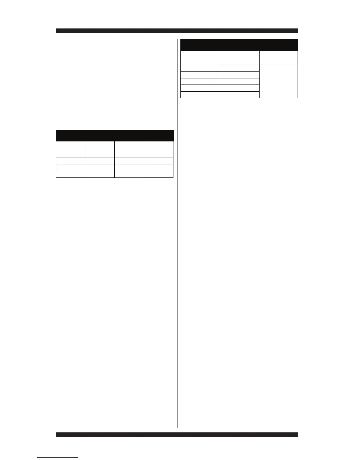
TEMP.
°F (°C)
RES.
RANGE
k ohms
TEMP.
°F (°C)
RES.
RANGE
k ohms
50° (10°) 19.0–22.0 80° (27°)8.5–10.5
60° (16°) 14.8–16.8 90° (32°)6.8–8.8
70° (21°)11.5–13.5 100° (38°)5.0–7.0
OUTLET THERMISTOR RESISTANCE
If the temperature is not reached within
~7 minutes, check voltage level and vent
blockage, and then retest.
If the temperature probe does not agree
with temperature setting, replace the outlet
thermistor.
If the temperature probe confirms the
temperature setting, retest at a different
temperature setting.
5. If the preceding steps did not correct the
problem, replace the CCU.
Inlet Thermistor
NOTE: On the electric dryer, the inlet thermistor
is part of the high thermostat assembly (see
figure 20a, page 14). On the gas dryer, the inlet
thermistor is located below the CCU bracket
at the drum inlet duct (see figure 25, page 23).
The CCU monitors the inlet temperature using
the inlet thermistor. The inlet thermistor (along
with the outlet thermistor) is used to detect air
flow, and assists in calculating load size.
3Quick Check: Inlet thermistor readings in °F,
°C, and resistance are provided in “Service
Diagnostics ➔ Component Activation ➔
Inlet Thermistor.”
1. Unplug dryer or disconnect power.
2. Remove top panel to access the machine
electronics.
3. Remove connector P14 from the CCU and
measure the resistance between P14-1 and
P14-2 at the connector. The following tables
(electric & gas) give temperatures and their
associated resistance values.
NOTE: All thermistor resistance measurements
must be made while dryer is unplugged and
connector removed from CCU.
If the resistance is OK, the inlet thermistor
is good. Proceed to step 4.
If the thermistor resistance does not agree
with the table, replace the inlet thermistor.
TEMPERATURE
SETTING
HEAT TURNS OFF*
°F (°C)
HEAT TURNS ON
°F (°C)
High 155° ± 5° (68° ± 3°)
Medium 140° ± 5° (60° ± 3°)
Low 125° ± 5° (52° ± 3°)
Extra Low 105° ± 5° (41° ± 3°)
EXHAUST TEMPERATURES
10–15° (6–8°)
below the
heat turn off
temperature
Medium High 150° ± 5° (65° ± 3°)