PAGE 17
FOR SERVICE TECHNICIAN’S USE ONLY
DO NOT REMOVE OR DESTROY
4. Check P14-1 and P14-2 to dryer cabinet
ground. If either pin indicates continuity
to ground (short), replace wiring harness;
otherwise, proceed to step 5.
5. If the preceding steps did not correct the
problem, replace the CCU.
TEST #4b: Thermal Fuse
ELECTRIC DRYER: The thermal fuse is wired
in series with the dryer drive motor.
GAS DRYER: The thermal fuse is wired
in series with the dryer gas valve.
ALL DRYERS:
1. Unplug dryer or disconnect power.
2. Access the thermal fuse by removing
the front panel. See Dryer Disassembly
Instructions, page 24.
3. Using an ohmmeter, check the continuity
across the thermal fuse.
If the ohmmeter indicates an open circuit,
replace the thermal fuse.
TEMP.
°F (°C)
RES.
RANGE
k ohms
TEMP.
°F (°C)
RES.
RANGE
k ohms
68° (20°) 61.2–63.7 131° (55°) 14.5–15.3
77° (25°) 49.0–51.0 140° (60°) 12.1–12.8
86° (30°) 39.5–41.1 149° (65°) 10.2–10.7
95° (35°) 32.0–33.3 158° (70°)8.5–9.0
104° (40°) 26.1–27.2 167° (75°)7.2–7.6
113° (45°) 21.4–22.3 176° (80°)6.1–6.5
122° (50°) 17.6–18.5
ELECT - INLET THERMISTOR RESISTANCE
TEMP.
°F (°C)
RES.
RANGE
k ohms
TEMP.
°F (°C)
RES.
RANGE
k ohms
68° (20°) 57.5–67.6 131° (55°) 14.1–15.6
77° (25°) 46.1–53.8 140° (60°)11.8–12.9
86° (30°) 37.4–43.1 149° (65°)9.9–10.8
95° (35°) 30.4–34.7 158° (70°)8.4–9.0
104° (40°) 24.9–28.2 167° (75°)7.1–7.6
113° (45°) 20.5–23.0 176° (80°)6.0–6.4
122° (50°) 16.9–18.9
GAS - INLET THERMISTOR RESISTANCE
TEST #4c: Thermal Cut-Off
If the dryer does not produce heat, check the
status of the thermal cut-off.
1. Unplug dryer or disconnect power.
2. Access the thermal cut-off by removing
the front panel. See Dryer Disassembly
Instructions, page 24.
3. Using an ohmmeter, check the continuity
across the thermal cut-off. See figures 20a
and 20b, page 14, for location.
4. If the ohmmeter indicates an open circuit,
perform the following:
ALL DRYERS: Replace both the thermal
cut-off and high limit thermostat. Also, check
for blocked or improperly installed exhaust
system, and, on electric dryers, for heat
element malfunction.
TEST #4d: Gas Valve, Gas Dryer
3Quick Check: Heater activation and
related component attributes are provided
in “Service Diagnostics ➔ Component
Activation ➔ Heat On.”
1. Unplug dryer or disconnect power.
2. Access the gas valve by removing
the back panel. See Dryer Disassembly
Instructions, page 24.
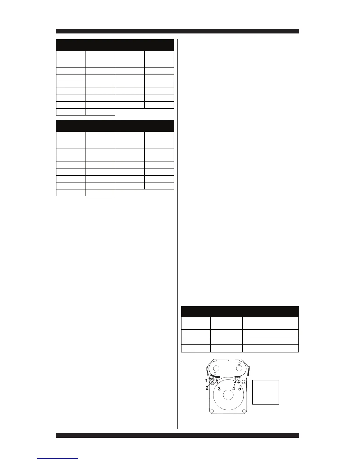
3. Use an ohmmeter to determine if a gas valve
coil has malfunctioned. Remove harness plugs.
Measure resistance across the terminals (see
figure 21). Readings should match those shown
in the following chart; if not, replace coils.
Pin 1 – Black
Pin 2 – Blue
Pin 3 – White
Pin 4 – Blue
Pin 5 – White
Figure 21 - Gas valve pinouts.
Coils Terminals
Resistance
in ohms
Hold 1 to 2 1400 ± 70
Assist 1 to 3 570 ± 28.5
Main 4 to 5 1300 ± 65
GAS VALVE RESISTANCE