PAGE 19
FOR SERVICE TECHNICIAN’S USE ONLY
DO NOT REMOVE OR DESTROY
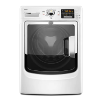
8. Measure the resistance across each of the
outermost contacts and the center terminal
(ground connection).
If a resistance less than infinity is
measured, replace the sensor harness.
9. If the moisture sensor diagnostic test
passes, check the outlet thermistor: TEST #4a,
page 15.
If the problem persists after replacing the
moisture sensor and thermistor, consider
adjusting the dryness level (see TEST #5a:
Adjusting Customer-Focused Dryness Level).
10. If the preceding steps did not correct the
problem, replace the CCU.
TEST #5a: Adjusting Customer-
Focused Dryness Level
NOTE: If the customer complains about the
clothes being damp and the moisture sensor
passes TEST #5: Moisture Sensor, step 3, the
total dry time can be lengthened (or shortened)
by changing the factory preset dryness setting.
1. Turn the cycle selector knob to an
automatic cycle.
2. From the Automatic Cycle Main Screen,
press and hold the dryness level button
(~3 seconds) until the “custom dryness
level” screen appears.
3. Select the desired dryness setting:
“factory preset” (standard auto cycle),
“15% More”, “30% More, “15% Less”, or
“30% Less”. The following screen will confirm
your selection. The selection will be stored on
the CCU and will be retained—even after a
power loss.
NOTE: If dryness setting is not selected within
6 seconds, it will time out and exit to the Main
Screen.
TEST #6: User Interface (UI)
This test is performed when any of the
following situations occurs during the “Service
Diagnostics ➔ Component Activation ➔ UI
Component Test.” (See page 5.)
3None of the indicators or display turn on
3Some buttons do not light indicators
3No beep sound is heard
NOTE: The User Interface, which includes the
Console, Modifier, and Center PCBs, must be
diagnosed and replaced as a single component.
None of the indicators or display turn on:
1. Unplug dryer or disconnect power.
2. Remove top panel to access the CCU.
3. Visually check that ALL CCU connectors
are fully inserted into the CCU (see page 9).
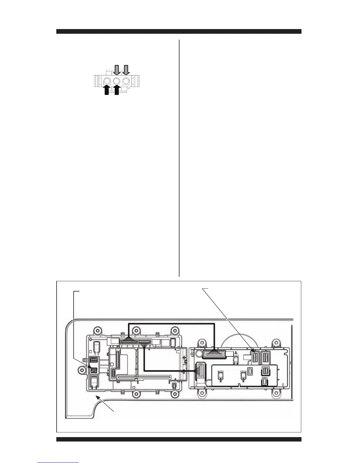
Figure 22 - User Interface (UI)
P07
P06
P02
P08
P09
P13
Center PCB
Console Assembly
P02 (from CCU):
Pin 1: Open
Pin 2: Ground
Pin 3: Data (WIDE BUS)
Pin 4: (+5V)
Pin 5: Open
P13 (to Drum Light):
See TEST #8: Drum Light, page 20.
Pin 1: Drum_L_P
Pin 2: Open
Pin 3: Drum_L_N
NOTE:
The User Interface (UI) must be replaced
as a single assembly. The UI includes the
Console, Modifier, and Center PCBs.
Modifier
PCB