7
THE PRESENT MANUAL IS PROPERTY OF THE MANUFACTURER. ANY REPRODUCTION, EVEN PARTIAL, IS PROHIBITED.
- 7 -
INSTRUCTIONS FOR USE
5.
7- 7 -
3.
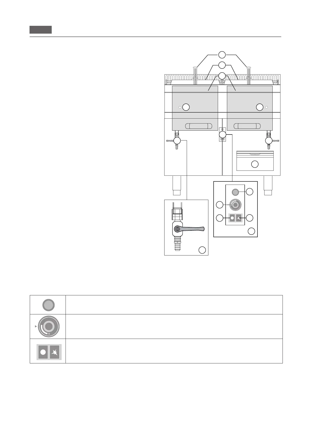
Knobs, keys and indicator light modes and functions
The layout of the keys in the gures is purely indicative and can be subject to variations.
Piezoelectric button (GAS). It performs one function:
1. When pressed, it produces the spark to ignite pilot light.
Thermostat knob (GAS).
It performs two different functions:
1. Emits gas in the circuit to ignite the burner.
2. Temperature regulation.
General switch-off key (GAS).
When pressed, it stops the gas ow to the pilot light.
Pilot light gas inlet key.
When pressed, it introduces gas in the ignition circuit for the pilot light.
1
2
3
4
5
6
7
8
1
2
3
4
5
6
7
8
5
1
2
7
4 4
6
1
2
3
4
5
6
7
8
B
C
A
5
D
3
6
6
Location of main components
The layout of the gures is purely indicative and can undergo
variations.
1. Lid
2. Rack
3. Cooking compartment
4. Opening for checking pilot light
5. Switch-on unit (see Knobs, keys and indicator
light modes and functions).
6. Gate valve for emptying oil from cooking
compartment
7. Burnt oil collection container