19
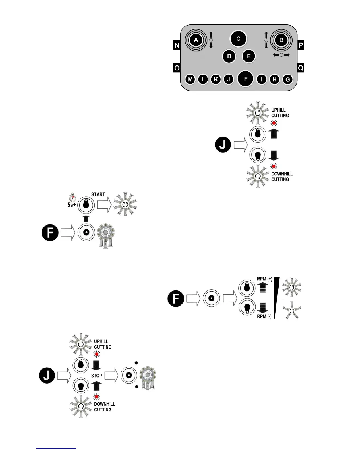
Flail Head Rotor Controls
Operation of the rotor is controlled by using
switches ‘J & ‘F ’. Each of the switch es
performs a dual function; switch ‘J’ is for pre-
setting the rotor cutting direction and for
switching the rotor off, and switch ‘F’ is for
starting the rotor and adjusting its speed.
Refer below for specific details of each
function.
Selection of Rotor Cutting Direction ►
Switch ‘J ’ is for pre-selection of the rotor cutting direction;
move the switch to the up posit ion for uphill cutting or to th e
down posit ion for downhill cutti ng - an led light will be
illuminated to indicate the di rection selected. Starting the
rotor is performed by operation of switch ‘F’ – see below.
◄ Rotor Start
Starting the rotor is by operatio n of switch ‘F’; set engine
speed to run at minimum revs before pressi ng the switch
upwards – the switch has a built in time delay to a void
unintentional rotor operation and must be held in pos ition
for at least 5 seconds ; release the switch as soon as the
rotor starts to run. Engine revs can now be increas ed
according to requirements.
Rotor Speed (RPM) ►
Once the rotor is running its speed can be
increased or decreased as required by
subsequent operations of switch ‘F’; eac h
upward or downwar d operation of the
switch will respective ly speed up or slow
down the rotor by a determined amount.
◄ Rotor Stop
To stop the rotor, first reduce the rotor speed to its
minimum using switch ‘F’ as des cribed above, then
move Switch ‘J’ into the central ‘off’ position.
Note (Pre-June 2015 machines only);
In an emergency situation the rotor can be stopped
by use of the Emergency Stop Button ‘C’; this will
immediately switch off and deactivate all machine
functions completely, including the engine.
This feature is not applicable to later machines.