For the A-series type of mini chiller, the inter-connecting pipes between the two
compartments are the refrigerant pipes. For the B-series type, there is a water pipe in
between the two compartments.
Therefore, the detached installation of the A-series mini chillers is very similar to the
installation of a split type air-conditioning unit.
Note:
Gas line to be insulated with
tube insulation. Use the
correct size for each pipe, thickness
¼
”
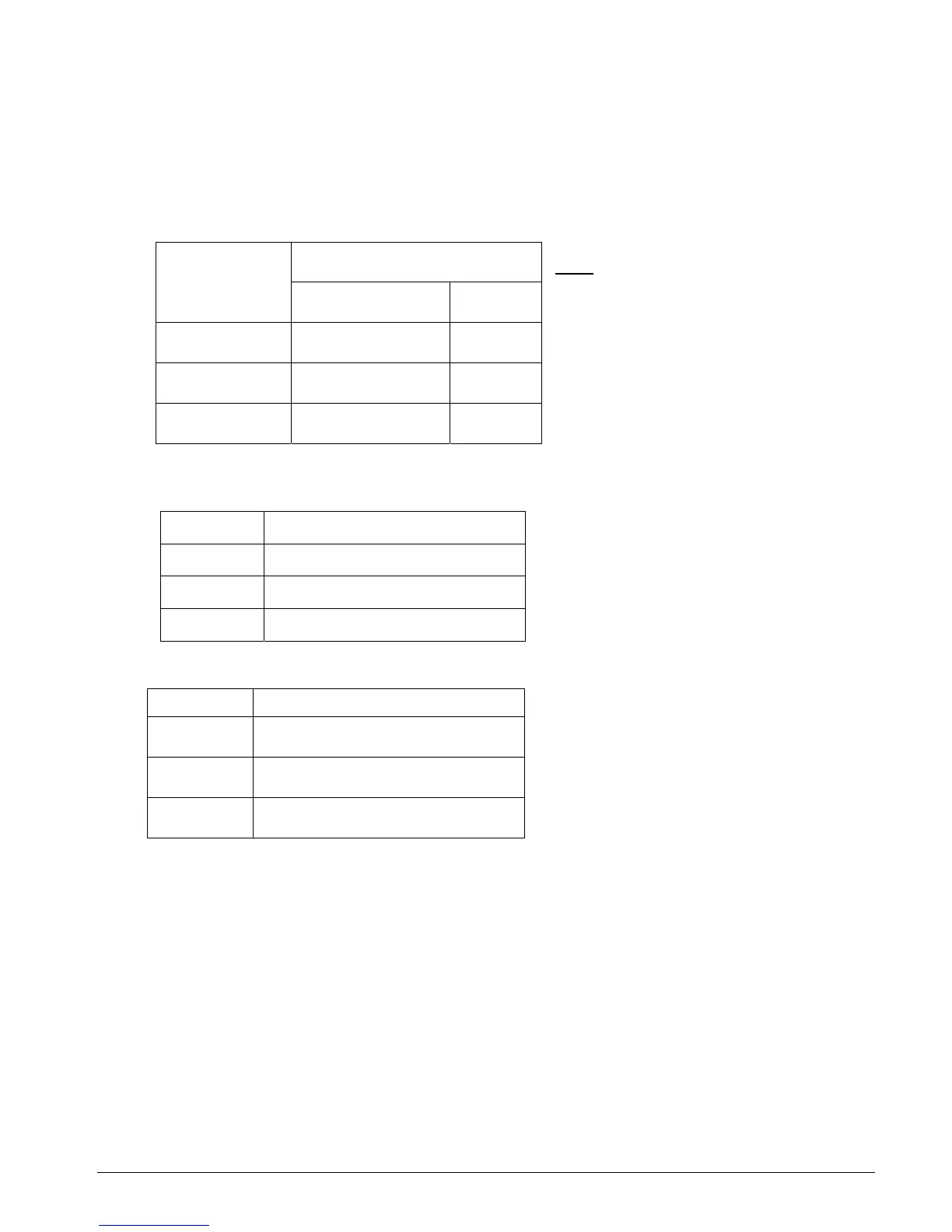
Refrig. Pipe size
Liquid Gas
AC 040A
3/8” ¾”
AC 050A
3/8” ¾”
AC 058A
½” ¾”
Take care of the following items [for detached A-series installations]:
Maximum pipe length,m
AC 040C
20
AC 050C
20
AC 058C
20
a) Do not allow excessive refrigerant pipe
length between the two compartments.
Always choose the shortest path.
Long piping will cause high pressure
drops and reduces the capacity of the
system. Use the following
recommendations:
Maximum elevation, m
AC 040A
10
AC 050A
10
AC 058A
10
b) It is possible to have the hydraulic kit
higher or lower than the refrigerant
compartment. Do not allow excessive
elevation between these two
compartments. Use the following
recommendations:
If the elevation exceeds the above recommendations, care must be taken to ensure sufficient oil
return to the compressor. Use oil traps (one every 30ft height interval) or oil separators, if
necessary.
c) The longer pipe lengths will require more refrigerant charge for optimum
performance.
Recommendation: Additional 50g (R-22) for every 1 meter of connecting pipe length.
Similarly, additional refrigerant oil charge may be required.
Section 1 Page 7