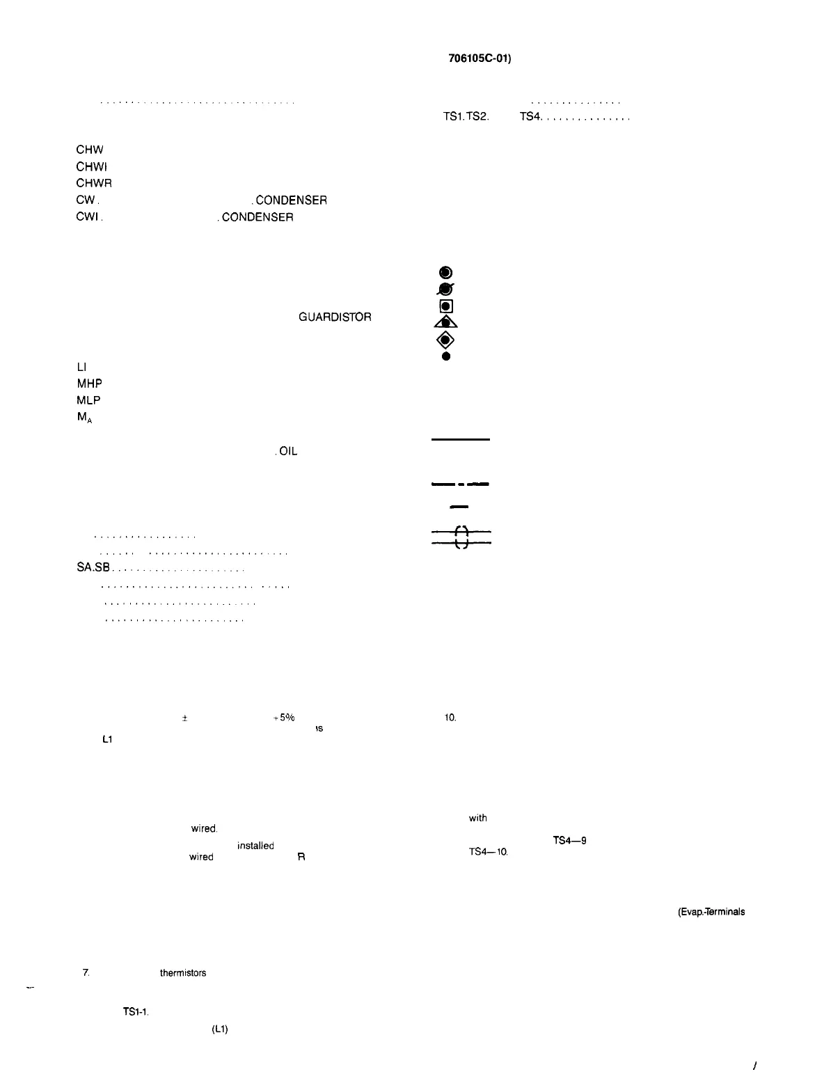
Figure 13. Legend-Symbols and Wiring Schematic Notes (Dwg. No.
706105C-01)
__
LEGEND
A.
..........................
ALARM, RELAY COIL
CAP. ..................................
CAPACITOR
Cl3
........................... CIRCUIT BREAKER
CHW
.....................
EVAPORATOR FLOW SWITCH
CHWI
..................
EVAPORATOR WATER INTERLOCKS
CHWR
...................
EVAPORATOR WATER RELAY
CW.
..................... .CONDENSER
FLOW SWITCH
CWI.
................. .CONDENSER
WATER INTERLOCKS
CWR
................... .COND. PUMP CYCLING RELAY
Cl ...............
COOLING TOWER FAN RELAY (STAGE 1)
C2
..............
COOLING TOWER FAN RELAY (STAGE 1)
G
........................
LIGHT (GREEN). MICRO STATUS
FT.
...................................
FAULT RELAY
GD
............... ................
GUARDISTOR
RELAY
HG
............................ HOT GAS SOLENOID
HP
.......................... HIGH PRESSURE RELAY
LI
.........................LIQUID INJECTION SOLENOID
MHP
.............. MECHANICAL HIGH PRESSURE SWITCH
MLP
...............
MECHANICAL LOW PRESSURE SWITCH
M,
............................
CONTACTOR AUXILIARY
MCR
..................
MTR. CONTR. RELAY (STARTER)
OC.
.......................
.OIL COOLER SOLENOID
OD
...................... OIL PRESS. DIFFERENTIAL SW.
OL
......................................
OVERLOAD
OP. ..........................
OIL PUMP CONTACTOR
OGT
................OIL GAUGE PRESSURE TRANSDUCER
PT
................
PNEUMATIC PRESSURE TRANSDUCER
R.
......
....................
LIGHT (RED). UNLOAD
SA.SB
....................
VANE CONTROL SOLENOIDS
SG.
.........................
....
SURGEGUARD RELAY
SW1
......................
PANEL START/STOP SWITCH
SW2
.......................
REMOTE START/STOP SWITCH
NOTES:
1.
2.
3.
4.
5.
6.
7.
_~
8.
9.
A separate 115 V
*
10% 60 HZ, 115 V +5% -10% 50 HZ single phase
10.
Voltage relay (VR) is used on units employing a CEO50 compressor. On
power supply is required. Fuse size requirement
IS
20 amp fusetron on
the remaining units VR leads 404 and 405 are deleted and lead 403 is
Ll only. L2 is a grounded neutral.
routed from terminal W to the capacitor.
A customer furnished 24 volt alarm relay coil may be connected between
terminals 50 and 68 of the control panel. The alarm coil will de-energize
when safety shut down occurs. Maximum rating of the alarm relay coil
is 25 VA.
11.
A customer supplied 4-20 MA signal can be supplied for chilled water
temperature reset or motor current limit reset. If the customer supplied
signal requires a power supply, then a 17 VDC unregulated power supp-
ly is available at terminal 67.
The compressor motor starters may be free standing or factory mounted.
If factory mounted, all the control wiring between the starter and the con-
trol panel is factory
wired.
Oil cooler solenoid is a factory
mstalled
option on some models. If field
supplied it must be
wired
to terminals B and
R
located in the lube con-
trol box.
12.
A signal converter is supplied on units where the starter is not furnished
with
a O-5 VDC or 4-20 MA DC load signal. If signal is available then
signal converter leads 617 and 616 are deleted and lead 521 is routed
from terminal 1 to
TS4-9
and lead 522 is routed from terminal 2 to
TS4-10.
Remote ON/OFF control of units for multiple unit applications can be ac-
complished by installing a set of dry contacts between terminals 9 and
64. If an additional point or ON/OFF control is required, remove jumper
J6 from terminal 64 and 65 and install the additional set of dry contacts.
Condenser water pump must cycle with the compressor by connecting
a 115V relay coil (CWR) with a maximum rating of 25 VA between ter-
minals 35 and 44.
13.
Water flow protection for both the evaporator and condenser must be pro-
vided. This protection shall consist of a flow switch or differential pressure
switch wired between terminals 10 and 62 for the evaporator, and 10 and
60 for the condenser. In addition each pump starter shall have a set of
auxillary contacts wired to the following terminals
(Evap.-Terminals
62 and
63: Condenser-Terminals 60 and 61).
Three or four thermtstors may be used depending on motor size and type.
Surgeguard relay is not used on units employing a CEO50 compressor.
On these units lead 614 is routed directly from guardistor relay terminal
1 to
TSi-1.
Liquid injection solenoid (Ll) and hot gas solenoid (HG) are found only
on units supplied with these options.
14.
A customer furnished 115 V evaporator water pump relay (CHWR)
may
be connected between terminals 36 and 44. This relay will energize
anytime the control requires the evaporator
water pump to be energiz-
ed. The maximum rating of this coil is 25 VA.
15.
Condenser water temperature control can be obtained by connecting two
customer furnished staging relays between terminals 39 and 45 for the
first stage and 38 and 45 for the second stage. The maximum rating of
these coils is 25 VA.
TR-1. TR-2. TR.3
..............
TRANSFORMER (24 VAC CT)
TSl.
TS2. TS3. TS4.
..............
DAUGHTERBOARD CONN.
TO
vc
VR
Y.
%
2
0
a
0
+
3
TIMED OPEN CONTACTS
VANE CLOSE SWITCH
VOLTAGE RELAY
LIGHT (YELLOW). LOAD
TERMINAL SYMBOLS
CONTROL BOX TERM. FACTORY WIRING
CONTROL BOX FIELD CONN. TERM.
LUBE BOX TERMINAL
STARTER TERMINAL
LEAD/LAG TERMINAL
UNIDENTIFIED TERMINALS
IDENTIFIED TERMINALS
AUTOMATIC RESET
MANUAL RESET
THERMISTOR
FACTORY WIRING
----- FIELD WIRING
-
-
-
STARTER WIRING
---
-
OPTIONAL WIRING
__H_
CABLE-TWISTED. SHIELDED
_tf_
AND JACKETED PAIR
IM 403
/
Page 13