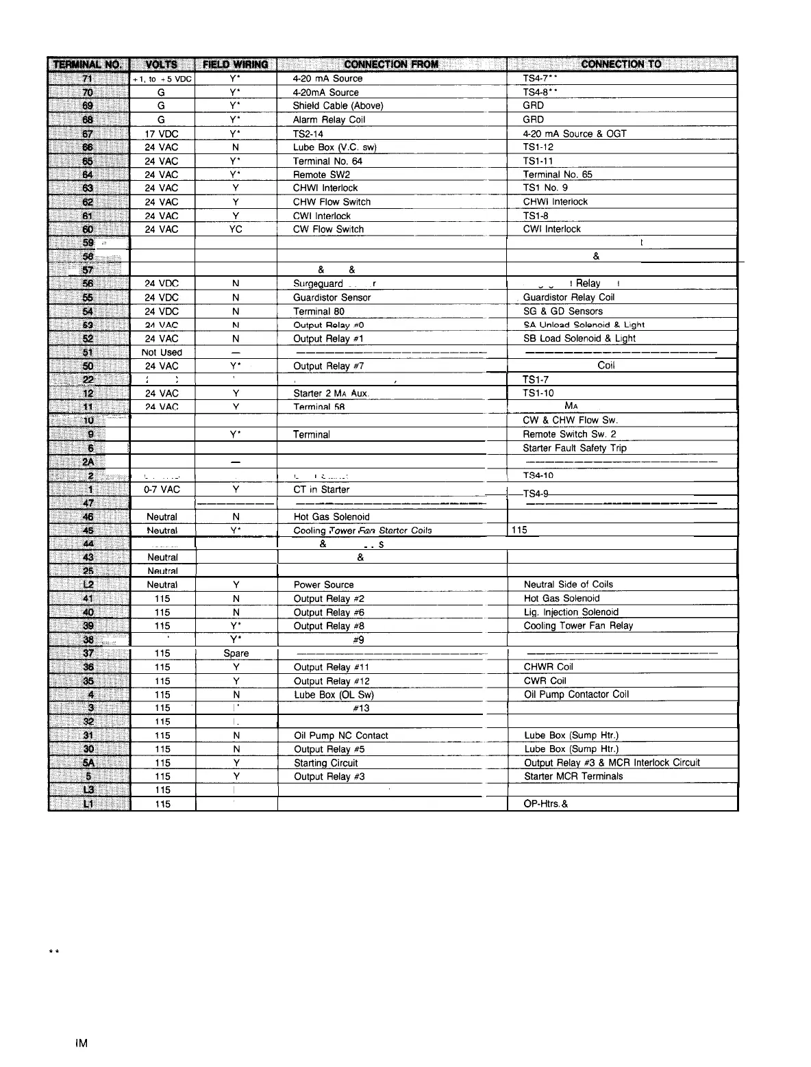
Table 6. Field Connection Terminal Strip
0
24 VAC
N
Lube Box (O.D. SW)
Corn-Term OP Aux. Contact
24 VAC
N
Term 78
Lube Box (O.D.
&
VC SW)
I,--’
24 VAC
N
MHP
&
MLP
&
Lube Box (O.D. SW) Fault Relay Coil
?ouard
Sensor
Suraeauard Relav
Coil
24 VAC
Y
Starter Fault Safety Trip
1
TSl-7
I
--------------------
/
Alarm Bell Relay
Co11
1
TSI-10
1
Starter 2
MA
Aux.
24 VAC Y Terminal
58
24 VAC
Y’
Terminal
58
L
24 VAC
Y Terminal 58
NIA
-
--------------------
O-7 VAC Y CT in Starter
1
Spare
________
__--_______-_-_-----
________------------
1
Neutral
1
,
“““““y
I
“..Vl
I
YII
Y
1
CWR
&
CHWR Coil
j
TS4-9
115 Neutral
I
115
Neutral
115 Neutral
~~
s
N
I
Lube Box (OP
&
Htrs.)
1
115 Neutral
Y
1
Starter MCR Coils
115 Neutral
:,~
1
115
Y’
1
Output Relay
ri9
Cooling Tower Fan Relay
I
N
Output Relay
#13
N
1
Oil Pump Contactor
]
Lube Box (OL SW)
]
Lube Box (OL Htr.)
N
3 Amp Circuit Breaker
Y
Control Power Source
115 Volt Power Circuits
OP-Htrs.
&
Circuit Breaker
NOTES:
Red Leads are 115 volt power
Yellow Leads are 24 volt power
White Leads are neutral ground
l Asterisk after Y in the Field Wiring column indicates that the device is an option. If the option is elected, Field Wiring is required
Field Wiring Required: Y = Yes; N = No
**
Terminals 70 to 71 include a 250 ohm resistor wired to produce a one to five volt control signal.
Page 14 I
IM
403