STARTING THE CENTRIFUGAL COMPRESSOR
Prior to starting the compressor, all procedural steps normally
associated with starting a newly installed machine must be
followed. For detailed recommendations, see
McQuay
SM001
and
IM
392 covering general start-up and the IQ-1000 solid-
state overload.
The proper direction of compressor motor
rotation
is vital,
and may be determined:
1. By means of a phase sequence test device.
2. By “bumping” the motor momentarily while visually obser-
ving the direction of the motor rotation.
With a
MicroTech
control panel, a machine may be
“bumped” only after all other start-up steps are completed.
by starting the machine with a 115 volt control lead and
pushbutton switch connected between terminals 25 at the
starter and 25 at the
MicroTech
control panel. The normal in-
terconnecting lead must be disconnected at either end and
the end taped temporarily.
The pushbutton switch should be a thumb-held button.
pressed and held to complete the circuit, suitable for 115 volts.
50 VA. It should be connected to 115 volt wiring long enough
to reach comfortably between the control panel connection
and a point at the compressor motor end cover where the start-
up technician can interrupt motor power instantly as the motor
begins to turn.
The sequence of timed functions such as “evaporator pump
on”,
"
waiting for load”, and “oil pump” pre-lube provide ade-
quate time for the technician to get into place at the motor
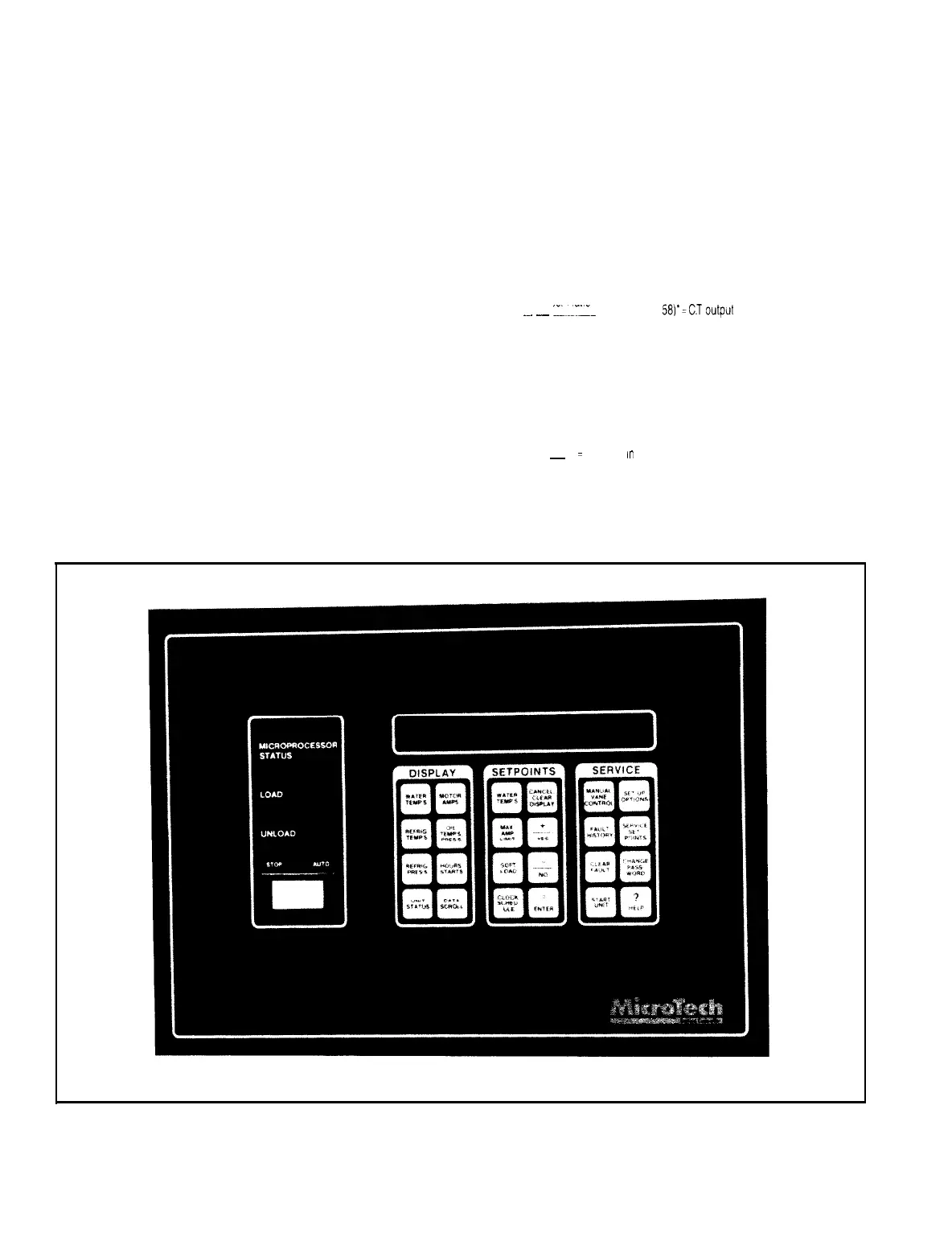
Figure 20. Keypad.
end cover sigh: glass. The direction of the motor rotation can
now be determined within a few electrical cycles after the MCR
coils close energizing the compressor. The technician should
then immediately release the “bump” switch, opening the cir-
cuit to the MCR relays and stopping the compressor.
Following completion of this last verification step (direction
of motor
rotation),
shut off the control circuit power at its
source. disconnect the “bump” switch wiring and reconnect
conventional control wiring.
Prior to re-connecting control power and energizing the
compressor power
circuit,
it is often possible and desirable
to set the current transformer circuits’ variable reisistor follow-
ing a quick
calculation.
Using the compressor RLA, and the
current transformer’s primary to secondary ratio, calculate the
resistance
in
ohms required to produce 5 volts AC.
Transf.
Sec.
Ratio
1
RLA
x
.~.
_
i._.__
x
j1.0,
.50
or
581’=CT
output
amps
Transf.
Pr
imary
Ratio
*
If the
current
transformer IS
in
the main
line
use 10; use 058
if
the CT IS
in
a phase leg
(Star-Delta
starters): use
.50
if
dual conductors are used on
across the
line
or,
autotransformer
starters and only one lead out of
six
is
pass-
ed through the
CT
2
Calculate
the
required ohms from the CT output amps as
follows
5 Volts
~
=
Resistance m
ohms
CT
output
amps
Since the MicroTech panel will accept between 5.0 and 7.0 volts
AC, recalculate step 2) using 7 volts
Page 20
/
IM
403