Figure
21. IQ-1000.
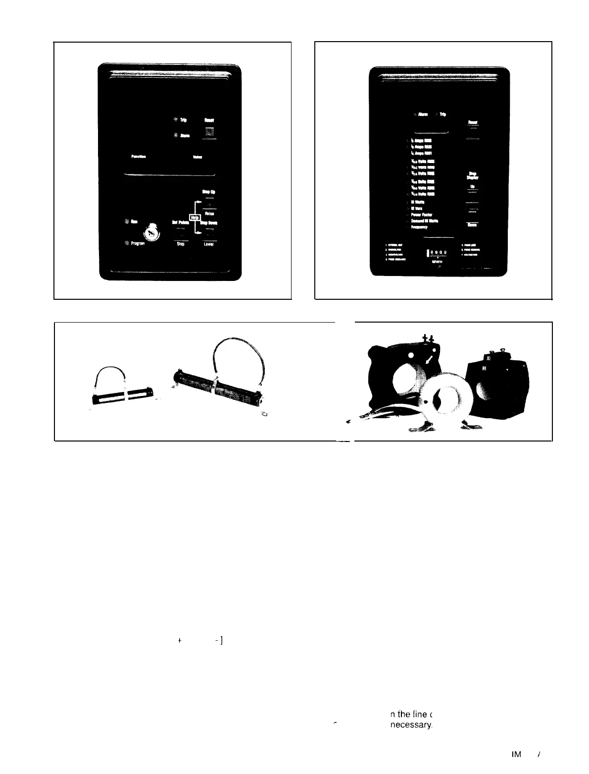
Figure 22 IQ-Data Pius.
F
igure
23. Typical Variable Resistor
&
Typical Current Transformers.
--
c
--
NOTE: If the unit has 2 resistors in parallel providing the AC
voltage signal, see Catalog
SM001
for calculation of the prin-
cipal resistance.
Using an ohmmeter, set the variable resistor for a resistance
between the two values calculated.
Reconnect any loose leads and connect both iines and con-
trol
power.
1.
2.
3.
4.
5.
‘Close all interlocks and switches to energize the com-
pressor motor.
Connect an amprobe around the line or phase leads to
the motor at the motor starter
Note the compressor motor rated load amps (or required
phase amps to equal motor rated load amps)
Press the “manual vane control” switch on the control
panel keypad. If the display requests a password input.
comply with the operator or service password. If the
display begins blinking
“[
+
]
load,
[
-]
unload” the unit
will be in a hold position.
Press the display section “motor amps” keypad once to
display “motor percent RLA
=
XX%
The
message wili
be blinking indicating a continuance of
the
manual vane
control mode.
DO NOT watch the
MicroTech
display for this step. Bring
the amps drawn by the compressor motor up to Rated
7.
8.
9.
10
Load
Amps, (nameplate RLA).
Stop loading the compressor at the design
RLA.
NOTE;
when
neither the
“+/Yes”
nor
“-/No”
keypad is being
pressed
the compressor vanes will be in a hold position
if
the
display is blinking.
If for
some
reason, a further “lock” on the RLA hold
posi-
tion
s
desired the needle valves in the
SA-SB
solenoid
ports
may be closed.
If the 5 to 7 volt AC signals’ resistance was not calculated
as stated previously, with the compressor drawing rated
load amps, carefully and cautiously adjust the starter’s
variable resistor to obtain a 5 to 7 volt AC signal between
terminals 1 and 2 (or 2A) on the
MicroTech’s
field
con-
nect
on
terminal strip. (see
SM001.)
With
the line ammeter showing Rated Load Amps, and
5 to
7
volts AC present at terminals 1 and 2 (or 2A) as
notes
above, use a small screwdriver at the trim pot of
the
si
gnal converter board in the
MicroTech
panel to dial
17’
a
display
reading of 100% amps. When this reading
is
obtained,
the signal converter will be delivering +4
volts
DC
to the Microprocessor daughter board TS4
ter-
minal
No 9.
If
the
display reads 100% amps at actual compressor
RLA
as
read on the
,lne
connected ammeter, no further
adjustment
IS necerrratr
r
.
IM
403
/
Page 21